
PHYS-131 · Lesson 12 of 12 · 28 min
Case studies and course project
This course has developed electricity and magnetism from charges and fields through potential, Gauss's law and capacitance, to current, circuits and measurement, magnetism, induction and inductance, alternating current, electromagnetic waves and semiconductor devices. Real engineering systems use many of these at once. This lesson works through three case studies: supplying a home electric vehicle charger, transmitting power over long distances, and cleaning industrial exhaust with an electrostatic precipitator. Each shows how a few physical principles, chosen well, answer practical design questions and expose the trade-offs. The lesson then sets out the course project and looks ahead to the courses that build on this one.
Case study 1: a home electric vehicle charger
A Level 2 charger runs from a 240 V circuit (Lesson 9). Suppose it draws a continuous 40 A, so it delivers \(P = VI = 240 \times 40 = 9.6\) kW. The questions an engineer asks: how long will charging take, how thick must the supply cable be, and how much energy is lost on the way?
The cable resistance follows from \(R = \rho L/A\) (Lesson 5), with the current flowing 30 m out and 30 m back. The voltage drop IR reduces the voltage at the charger, and the power \(I^2R\) heats the cable. Electrical codes (the Canadian Electrical Code and the US National Electrical Code) also require the conductors to carry the current without overheating, treat EV chargers as continuous loads sized at 125% of their current, and limit voltage drop, typically to a few percent.
# Level 2 EV charger: 240 V, 40 A continuous, 30 m from the panel (60 m of conductor, out and back)
rho = 1.72e-8 * 1.2          # copper resistivity, ohm m, raised 20% for a warm conductor
V, I, run = 240.0, 40.0, 30.0
for area_mm2 in [6, 10, 16]:
    R = rho * 2 * run / (area_mm2 * 1e-6)
    drop = I * R
    loss = I**2 * R
    print(f"{area_mm2:2d} mm2 copper: R = {R * 1000:5.1f} mohm, drop {drop:4.1f} V ({100 * drop / V:.1f}%), "
          f"loss {loss:5.0f} W ({100 * loss / (V * I):.1f}% of {V * I / 1000:.1f} kW)")

battery_kWh, efficiency = 75.0, 0.90
print(f"Charging {battery_kWh:.0f} kWh at {V * I / 1000:.1f} kW and {efficiency:.0%} efficiency takes {battery_kWh / (V * I / 1000 * efficiency):.1f} h")
print(f"A 150 kW DC fast charger at 400 V supplies {150e3 / 400:.0f} A")6 mm2 copper: R = 206.4 mohm, drop 8.3 V (3.4%), loss 330 W (3.4% of 9.6 kW) 10 mm2 copper: R = 123.8 mohm, drop 5.0 V (2.1%), loss 198 W (2.1% of 9.6 kW) 16 mm2 copper: R = 77.4 mohm, drop 3.1 V (1.3%), loss 124 W (1.3% of 9.6 kW) Charging 75 kWh at 9.6 kW and 90% efficiency takes 8.7 h A 150 kW DC fast charger at 400 V supplies 375 A
A 6 mm² cable would lose 3.4% of the power and drop 8 V; 10 mm² keeps the drop near 2%; 16 mm² halves the loss again at higher cost. Charging a 75 kWh battery takes almost 9 hours, overnight. A DC fast charger at 150 kW must supply 375 A at 400 V, which is why its cables are thick and often liquid-cooled, and why fast-charging sites need dedicated medium-voltage connections and transformers (Lesson 7). Within the car, the battery's internal resistance (Lesson 6) also heats it during fast charging, so battery management systems taper the current as the battery fills and warms.
Worked problem
The household energy view
A car uses 18 kWh per 100 km. How much electricity does 15 000 km a year need, delivered through a 90% efficient charger, and what does it cost at $0.14/kWh?
Show solution
- Energy into the battery: \(15\,000 \times 0.18 = 2700\) kWh.
- From the grid: 2700/0.90 = 3000 kWh.
- Cost: 3000 × 0.14 = $420.
Answer: About 3000 kWh a year, roughly a third of a typical Canadian home's annual electricity use, costing about $420 at this rate. Spread over overnight hours, it fits most household services, but many homes charging at once in early evening would load local distribution transformers, which is why utilities encourage off-peak charging.
Case study 2: why transmit at high voltage?
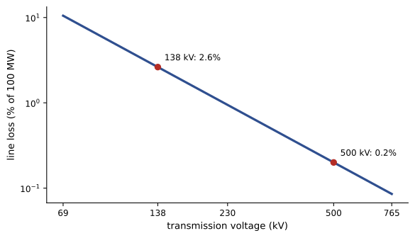
A generating station must send 100 MW to a city 100 km away over a three-phase line whose conductors each have a resistance of 0.05 Ω/km. For three-phase power (Lesson 9), the line current is \(I = P/(\sqrt{3}\,V\cos\phi)\), and the loss is \(3I^2R\).
Worked problem
Line losses at two voltages
Compare the line current and resistive loss at 138 kV and 500 kV, with a power factor of 1.
Show solution
- R per conductor = 0.05 × 100 = 5.0 Ω.
- 138 kV: \(I = 100 \times 10^6/(\sqrt{3} \times 138\,000) = 418\) A; loss \(3 \times 418^2 \times 5.0 = 2.6\) MW, or 2.6%.
- 500 kV: \(I = 115\) A; loss \(3 \times 115^2 \times 5.0 = 0.20\) MW, or 0.2%.
Answer: Raising the voltage 3.6 times cuts the current by the same factor and the loss by its square, about 13 times. This is why bulk power moves at hundreds of kilovolts, and why the transformer, which changes voltage efficiently (Lesson 7), made AC the standard. Very long lines, including some that bring hydroelectric power from northern Quebec and Manitoba, use high-voltage DC instead, which avoids reactive power and some losses over very long distances, at the cost of converter stations at each end.
Higher voltage brings its own physics problems, all from this course. The surface field on the conductors must stay below corona onset (Lesson 3), so high-voltage lines use bundled conductors. Clearances to the ground and to towers must prevent breakdown of the air (Lesson 2). Insulators must withstand both the operating voltage and lightning surges. And the line's inductance and capacitance (Lessons 4 and 8) create reactive power that must be managed, which grows with length. The magnetic field under a line is modest: from Ampère's law (Lesson 7), 418 A at 15 m gives \(\mu_0I/(2\pi r) = 5.6\) µT for a single conductor, about a tenth of the Earth's field, and the fields of the three phases partly cancel.
Case study 3: an electrostatic precipitator
Cement kilns, pulp mills, smelters and biomass boilers emit fine dust that harms health. An electrostatic precipitator removes it using nothing but electric fields. Flue gas passes between grounded collecting plates and fine discharge wires held at tens of kilovolts negative. The very high field near the thin wires (Lesson 3) produces a corona that fills the space with negative ions; the ions stick to dust particles and charge them; and the electric field between wire and plate (Lesson 2) drives the charged particles to the plates, where they are periodically knocked off into hoppers.
Worked problem
How fast do particles move?
A 2 µm diameter particle acquires a charge of about 1 × 10⁻¹⁶ C in a field of 300 kV/m. Air viscosity is 1.8 × 10⁻⁵ Pa·s. Find the electric force and the particle's drift (migration) velocity, using Stokes's law for drag, \(F = 6\pi\mu rv\).
Show solution
- Electric force: \(F = qE = 10^{-16} \times 3 \times 10^5 = 3 \times 10^{-11}\) N (Lesson 2).
- At steady drift, drag balances it: \(v = qE/(6\pi\mu r) = 3 \times 10^{-11}/(6\pi \times 1.8 \times 10^{-5} \times 10^{-6}) = 0.09\) m/s.
Answer: About 9 cm/s, tiny compared with the gas speed of a meter or two per second along the plates, but enough: a particle crossing a 0.15 m gap needs under 2 s, and the plates are long enough to give it that time. The electric force is several hundred times the particle's weight, which is why electrostatic collection works so well for fine particles that cyclones and gravity settling cannot catch.
The overall collection efficiency is estimated by the Deutsch equation, \(\eta = 1 - e^{-wA/Q}\), where w is the migration velocity, A the total collecting plate area and Q the gas flow rate. With w = 0.09 m/s, Q = 300 m³/s and A = 10 000 m², \(wA/Q = 3.0\) and η = 95%; doubling the plate area raises it to 99.75%. Because efficiency depends exponentially on area, the last fraction of a percent is expensive, and precipitators are often among the largest structures at an industrial plant. Their performance also depends on the electrical resistivity of the dust, which controls how charge leaks away on the plates.
The method behind the case studies
The three studies followed the same pattern:
- Identify the physical quantities that matter: current and resistance for heating, voltage for losses, field strength for breakdown and particle motion.
- Choose the simplest model that captures them: Ohm's law and I²R, three-phase power formulas, Coulomb force against Stokes drag.
- Check against limits set by physics and by codes: breakdown fields, voltage drop limits, conductor ampacity, emission standards.
- Explore the trade-offs: thicker cable against cost, higher voltage against insulation and corona, plate area against efficiency.
- Sanity-check orders of magnitude: a charging time, a percentage loss, a drift speed.
The course project
Choose one of the following problems, or propose your own of similar scope with your instructor's approval, and prepare a report with your model, calculations, a measurement or simulation where possible, checks and conclusions.
- Project A: Home electrical design. For a real or hypothetical home, estimate the loads (including an EV charger or heat pump), select conductor sizes for two circuits from first principles (resistance, voltage drop, loss), compare with code requirements, and estimate annual energy use and cost.
- Project B: Measurement and sensing. Build or simulate a sensor circuit (a strain gauge bridge, a thermistor divider or a Hall-effect current sensor), predict its output with the theory of this course, measure or simulate it, and analyze the sources of error including meter loading.
- Project C: Power systems. Compare transmitting a given power over a given distance at several voltages, including resistive loss, corona considerations, conductor and insulation requirements, and the effect of power factor, and recommend a voltage with reasons.
- Project D: Energy storage and conversion. Compare capacitors, batteries and an inductive storage scheme (or a solar module and battery system) for a defined application, using energy, power, efficiency and cost, and recommend a design.
Every report should include circuit or field diagrams, state assumptions and their effect, check units and orders of magnitude, compare at least one result with an independent estimate or measurement, and observe electrical safety in any practical work.
Looking ahead
Electricity and magnetism underpin electrical, computer and much of mechanical and civil engineering. Circuit analysis courses (ELE-202 and ELE-203) develop the methods of Lessons 5, 6 and 9 systematically; electromagnetics extends Gauss's, Faraday's and Ampère's laws to fields and waves in full (MATH-209 lays the mathematical groundwork); electric machines and power systems build on induction, transformers and three-phase power; electronics builds on the semiconductor devices of Lesson 11. For every engineer, the principles of this course explain how the power and information systems they depend on actually work.
Common mistakes
MistakeCounting only one conductor's length in a voltage drop calculation.
InsteadCurrent flows out and back; include both conductors.
MistakeSizing cable on voltage drop alone.
InsteadAlso meet the code ampacity rules, including 125% for continuous loads.
MistakeThinking higher voltage reduces losses in proportion to voltage.
InsteadFor fixed power, loss falls with the square of voltage.
MistakeIgnoring corona and insulation when choosing a transmission voltage.
InsteadHigher voltage needs larger conductors or bundles, clearances and insulators.
MistakeExpecting precipitator efficiency to rise linearly with plate area.
InsteadEfficiency approaches 100% exponentially; the last fraction costs most.
Summary and key terms
- An EV charger at 240 V and 40 A delivers 9.6 kW; cable losses I²R and voltage drop guide conductor size.
- DC fast charging needs hundreds of amperes and dedicated supply infrastructure.
- For fixed power, transmission loss falls as 1/V²: 138 kV to 500 kV cuts loss about thirteenfold.
- High-voltage design must manage corona, clearances, insulation and reactive power.
- Electrostatic precipitators charge particles by corona and drift them to plates at v = qE/(6πμr).
- Collection efficiency follows the Deutsch equation η = 1 − e^(−wA/Q).
- The method: identify the key quantities, choose a simple model, check limits, explore trade-offs, sanity-check.
- Level 2 charger
- An EV charger supplied from a 240 V AC circuit.
- Voltage drop
- The reduction of voltage along a conductor due to its resistance, IR.
- Ampacity
- The current a conductor can carry continuously without exceeding its temperature rating.
- Continuous load
- A load expected to run at full current for three hours or more.
- Line loss
- Power dissipated in the resistance of transmission conductors.
- HVDC
- High-voltage direct current transmission, used for very long or undersea links.
- Electrostatic precipitator
- A device that removes particles from gas using electric charging and fields.
- Migration velocity
- The drift speed of a charged particle toward the collecting plates.
- Deutsch equation
- η = 1 − e^(−wA/Q), the collection efficiency of a precipitator.
Practice problems
Work each problem on paper first, then reveal the answer to check.
Find the power of a charger drawing 32 A at 240 V.
Show answer
7.68 kW.
Find the resistance of 50 m (out and back, 100 m of conductor) of 10 mm² copper (ρ = 2.06 × 10⁻⁸ Ω·m).
Show answer
0.206 Ω.
What voltage drop does 32 A cause in that cable?
Show answer
6.6 V (2.7%).
How long does a 60 kWh battery take to charge from empty at 7.68 kW with 90% efficiency?
Show answer
8.7 h.
Find the line current for 200 MW at 230 kV three-phase, power factor 1.
Show answer
502 A.
If the transmission voltage doubles at the same power, what happens to the loss?
Show answer
It falls to a quarter.
Find the magnetic field 20 m from a long conductor carrying 600 A.
Show answer
μ₀I/(2πr) = 6.0 µT.
A particle of charge 2 × 10⁻¹⁶ C is in a 400 kV/m field. Find the force.
Show answer
8 × 10⁻¹¹ N.
With w = 0.1 m/s, A = 6000 m² and Q = 200 m³/s, find the precipitator efficiency.
Show answer
1 − e⁻³ = 95%.
What plate area would give 99% efficiency in that case?
Show answer
wA/Q = 4.6: A = 9200 m².
Lesson quiz · 5 questions
Score 60% or more to complete this lesson.
Create a free account to save your progress, take quizzes and earn a certificate.