
PET-430 · Lesson 7 of 12 · 19 min
CO2 EOR in practice
Carbon dioxide flooding is the most widely applied light oil EOR method in North America, with a history that goes back to the SACROC unit in west Texas, where CO2 injection began in 1972. Its attractions are clear from Lesson 6: at moderate pressure CO2 develops miscibility with most light oils, it swells the oil and cuts its viscosity, and it is far cheaper per reservoir volume than hydrocarbon solvent. Its difficulties are just as clear: it is very mobile, it must be bought and transported, much of it comes back with the produced oil and must be recycled, and it is corrosive in the presence of water. This lesson is about how operators deal with each of these in practice, and about the storage of CO2 that accompanies every CO2 flood.
Carbon dioxide as an injectant
CO2 has a critical temperature of 31.1 °C (88 °F) and a critical pressure of 7.38 MPa (1,071 psia). At the temperatures and pressures of most oil reservoirs it is a supercritical fluid with a density of 500 to 800 kg/m³, liquid-like enough to extract intermediate hydrocarbons efficiently, but with a viscosity of only 0.04 to 0.08 cp. It is far more soluble in oil than methane is. At 2,000 psia and 140 °F, a light oil can dissolve enough CO2 to swell by 20 to 40 percent and to drop its viscosity by half or more, even when miscibility is not achieved. CO2 also dissolves in water, forming carbonic acid, which corrodes carbon steel and can dissolve carbonate minerals near injectors.
Mobility control: water alternating gas
Continuous CO2 injection gives early breakthrough and poor sweep, for the reasons covered in Lesson 3. Almost all CO2 floods therefore use water alternating gas (WAG) injection: slugs of CO2 alternate with slugs of water. The water lowers the total mobility of the injected fluids, because when both phases flow each has a reduced relative permeability, and it moves preferentially into the lower part of the section, offsetting gravity override. A typical design injects a total CO2 volume of 0.4 to 1.0 hydrocarbon pore volumes (HCPV) over the life of the flood, in slugs of 1 to 3 percent HCPV, with a WAG ratio of water to CO2 reservoir volumes near 1:1. Many projects begin with a larger CO2 slug to build an oil bank and then taper: the WAG ratio is raised over time to save CO2 once the main oil bank has been produced.
WAG has costs as well as benefits. Water injected after CO2 can shield oil from contact with the gas in water-wet rock, which reduces the microscopic efficiency. Injectivity often falls when water follows CO2, because three-phase relative permeabilities are lower than two-phase ones, and the injection pressure limit can then cap the injection rate. The best WAG ratio and cycle length are found by compositional simulation and refined in the field by watching pattern response. Foams, made by injecting surfactant with the CO2, and conformance gels in thief zones are used where WAG alone does not control mobility.
CO2 supply
A CO2 flood needs large volumes of affordable CO2, delivered by pipeline at high pressure. In the United States the industry grew on natural CO2 from geological sources such as the McElmo Dome and Doe Canyon fields in Colorado, Sheep Mountain in Colorado and Bravo Dome in New Mexico, which feed the Permian Basin through pipelines hundreds of kilometers long, and Jackson Dome in Mississippi, which supplies the Gulf Coast. Anthropogenic CO2 from natural gas processing, ethanol and fertilizer plants, coal gasification and power plants has become increasingly important as capture technology and tax credits have improved its economics.
North Dakota is linked to Canada's best-known CO2 flood. Since October 2000, the Great Plains Synfuels Plant at Beulah, which gasifies lignite, has piped captured CO2 about 320 km to the Weyburn unit in southeast Saskatchewan, and since 2005 to the neighboring Midale unit. Within the United States, the Permian Basin floods built on natural CO2, while newer projects increasingly use captured CO2 from gas processing, ethanol and fertilizer plants. In the Williston Basin, CO2 floods of conventional Paleozoic reservoirs such as the Red River and Mission Canyon have been studied as candidates, with captured CO2 from ethanol plants and other sources discussed as supply.
Supply shapes project design. A flood that buys CO2 under a fixed take-or-pay contract must plan for a steady purchase rate for many years, so it develops patterns in phases, moving purchased CO2 to new patterns as the early patterns' recycle volumes grow.
Recycling and the CO2 balance
Between 30 and 70 percent of the injected CO2 eventually returns to the surface with the produced oil and water, the share rising as the flood matures. Because the CO2 is valuable, it is separated from the produced gas, dehydrated, compressed and reinjected. A mature CO2 flood is as much a gas processing operation as an oil field: produced gas may contain 80 to 90 percent CO2 together with methane and natural gas liquids, which are recovered as a by-product. The CO2 balance distinguishes two utilization ratios. Gross utilization is the total CO2 injected, purchased plus recycled, per barrel of incremental oil; net utilization counts only purchased CO2. Permian Basin floods have typically reported gross utilization of about 10 Mcf per barrel and net utilization of 4 to 8 Mcf per barrel, roughly 0.2 to 0.4 metric tons of purchased CO2 per barrel.
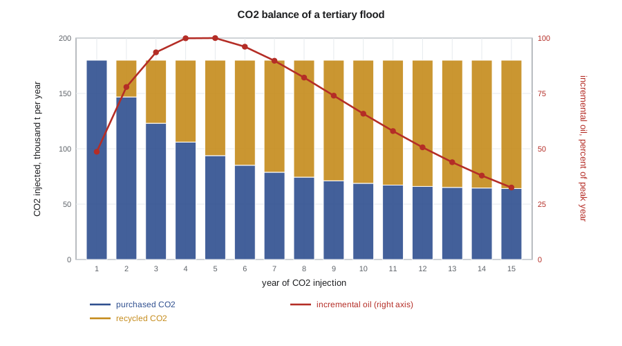
# CO2 balance of a tertiary flood: purchased, recycled and stored CO2, utilization and credit value.
import math
SI = False     # True: metric units, False: oilfield units
MCF_PER_T = 18.9                   # Mcf of CO2 per metric ton
gross = 180e3                      # CO2 injected per year, t (purchased + recycled)
target = 0.68e6                    # incremental oil over 15 years, m3
credit = 40.0 if SI else 85.0      # value per metric ton stored, dollars (assumed / 45Q for EOR)

years = range(1, 16)
shape = [y * math.exp(-y / 4.5) for y in years]
oil = [target * s / sum(shape) for s in shape]
rows, cp = [], 0.0
for y, o in zip(years, oil):
    rec = gross * 0.65 * (1 - math.exp(-(y - 1) / 3.0))
    buy = gross - rec
    rows.append((y, o, buy, rec)); cp += buy
co = sum(oil); stored = cp * 0.995
print(" yr   oil       purchased  recycled   (CO2 in kt)")
for y, o, b, r in rows[::2]:
    ov = f"{o / 1e3:6.1f} km³" if SI else f"{o * 6.2898 / 1e3:6.0f} Mbbl"
    print(f" {y:2d}  {ov}   {b / 1e3:7.0f}   {r / 1e3:7.0f}")
gu = gross * 15 / co; nu = cp / co
if SI:
    print(f"Gross utilization {gu:.2f} t/m³, net utilization {nu:.2f} t/m³ of incremental oil")
else:
    print(f"Gross utilization {gu * MCF_PER_T / 6.2898:.1f} Mcf/bbl, net {nu * MCF_PER_T / 6.2898:.1f} Mcf/bbl of incremental oil")
print(f"CO2 stored {stored / 1e6:.2f} Mt; at {credit:.0f} dollars per metric ton worth {stored * credit / 1e6:.0f} million dollars over 15 years")
print(f"Stored CO2 per unit of oil: {stored / co:.2f} t/m³" if SI else f"Stored CO2 per barrel: {stored / (co * 6.2898):.2f} t/bbl")yr oil purchased recycled (CO2 in kt) 1 198 Mbbl 180 0 3 381 Mbbl 123 57 5 407 Mbbl 94 86 7 365 Mbbl 79 101 9 301 Mbbl 71 109 11 236 Mbbl 67 113 13 179 Mbbl 65 115 15 132 Mbbl 64 116 Gross utilization 11.9 Mcf/bbl, net 6.0 Mcf/bbl of incremental oil CO2 stored 1.35 Mt; at 85 dollars per metric ton worth 115 million dollars over 15 years Stored CO2 per barrel: 0.32 t/bbl
The code reproduces the shape of real CO2 balances. Purchases fall by more than half as recycle grows, and the net utilization of about 6 Mcf per barrel, or 0.32 metric tons per barrel, is in the typical range. The purchased CO2 remains in the reservoir at the end of the flood, apart from small operational losses. That fact turns every CO2 flood into a CO2 storage project, whether or not that is its purpose.
Worked problem
Net utilization and storage
A CO2 flood buys 1.35 Mt of CO2 over its life and recovers 4.28 million barrels of incremental oil. Operational losses are 0.5 percent of purchases. Find the net utilization and the stored CO2 per unit of oil.
Show solution
- Net utilization is 1.35 × 10⁶ t / 4.28 × 10⁶ bbl = 0.315 t/bbl, or 0.315 × 18.9 = 6.0 Mcf/bbl.
- Stored CO2 is 1.35 × 0.995 = 1.343 Mt.
- Stored CO2 per unit of oil is 1.343 / 4.28 = 0.31 t/bbl.
Answer: Net utilization is about 6.0 Mcf/bbl, and almost all of it, about 0.31 t of CO2 per barrel of incremental oil, remains stored in the reservoir.
Incentives for CO2 EOR
The economics of CO2 EOR depend on CO2 cost and on policy. The federal 45Q tax credit pays the owner of capture equipment for each metric ton of CO2 captured and either stored in a dedicated geological formation or used, including in EOR, with monitoring and reporting requirements. For many years the credit for EOR use was lower than for dedicated storage, but legislation in 2025 raised it to parity, about 85 dollars per metric ton for qualifying projects. North Dakota has its own incentives for tertiary recovery and has taken primacy for permitting CO2 storage wells, which simplifies regulation of projects that store CO2. Across the border, Saskatchewan supports EOR through its royalty structure and a program of transferable credits that extends to CO2 pipelines.
Operations and storage
Facilities for CO2 floods must resist corrosion where CO2 and water meet: injection wells use corrosion-resistant alloys or lined tubing and CO2-resistant cement, and producers handle carbonic acid, scale and sometimes asphaltene precipitation, which CO2 can trigger in some oils. Old wellbores that penetrate the flooded zone are inspected and, where necessary, re-plugged, because they are the main potential leakage path for CO2. Safety systems deal with the asphyxiation hazard of CO2, which is heavier than air and pools in low areas, and with hydrogen sulfide where it is present.
Storage in EOR is called associated storage. Monitoring at Weyburn and Midale under the IEA Greenhouse Gas R&D Program project from 2000 to 2011 used repeated seismic surveys, soil gas sampling, groundwater chemistry and geochemical tracing to follow the injected CO2, and found no evidence that it had leaked from the reservoir. Published estimates put the eventual storage in the two units at about 40 million metric tons. ISO 27916, published in 2019, sets out how to quantify and document CO2 stored through EOR. The deeper science of trapping mechanisms, long-term monitoring and dedicated saline aquifer storage is the subject of PET-460.
For Ethan's study, the lesson is that a CO2 flood in the Mission Canyon pool is technically plausible but depends on a CO2 source. He adds a line to his task list: identify the nearest sources of captured CO2, their volumes and the pipeline distance.
Monitoring a CO2 flood
Surveillance of a CO2 flood builds on the waterflood tools of Lesson 5 and adds gas-specific measurements. Operators track the CO2 content of produced gas at each well, because a sudden rise marks breakthrough along a high-permeability path; they adjust the WAG ratio, cycle length or injection rate of the supporting injectors in response. Injection profiles are run during both water and CO2 cycles, since the two fluids often enter different intervals. Pattern-level CO2 balances, comparing CO2 injected and produced, identify patterns that are losing CO2 out of the pattern or cycling it inefficiently through a thief zone. In mature Permian floods, managing the WAG schedule pattern by pattern in response to these data has been one of the main ways operators reduce net utilization and keep CO2 working in the unswept parts of the reservoir.
Common mistakes
MistakeRunning continuous CO2 injection in a layered reservoir.
InsteadUse WAG, foam or conformance control to limit override and fingering.
MistakeConfusing gross and net utilization.
InsteadGross counts all CO2 injected; net counts only purchased CO2, which drives cost and storage.
MistakeAssuming produced CO2 can be vented.
InsteadProduced CO2 is separated, compressed and recycled; venting wastes injectant and adds emissions.
MistakeIgnoring legacy wellbores.
InsteadOld wells penetrating the flooded zone must be checked and re-plugged as part of the project.
Summary and key terms
- CO2 is supercritical at reservoir conditions, dense, very soluble in oil and of very low viscosity.
- WAG injection alternates CO2 and water slugs to reduce mobility and offset gravity override; ratios near 1:1 and total CO2 of 0.4 to 1.0 HCPV are common.
- CO2 comes from natural domes in the US and increasingly from captured sources, including the Beulah plant supplying Weyburn and Midale since 2000 and 2005.
- Recycled CO2 grows over the life of a flood; net utilization of about 4 to 8 Mcf per barrel is typical.
- Purchased CO2 is almost all stored, making CO2 EOR an associated storage project.
- Incentives include the US 45Q credit, now at parity for EOR, and Saskatchewan's royalty structure and credits; Canada's federal CCUS credit excludes EOR.
- WAG
- Water alternating gas: injection of alternating slugs of water and gas to control mobility.
- HCPV
- Hydrocarbon pore volume, the pore volume occupied by oil and gas.
- Gross utilization
- Total CO2 injected, purchased plus recycled, per unit of incremental oil.
- Net utilization
- Purchased CO2 per unit of incremental oil.
- Associated storage
- CO2 stored in a reservoir as a consequence of CO2 EOR.
- 45Q
- The US federal tax credit for captured CO2 that is stored or used.
- Tapered WAG
- A WAG scheme in which the water-to-gas ratio is raised over time to save CO2.
Practice problems
Work each problem on paper first, then reveal the answer to check.
Why does WAG improve sweep compared with continuous CO2 injection?
Show answer
Two-phase flow lowers total mobility, and the water sweeps lower layers that the gas overrides.
A flood injects 12 Mcf of CO2 per barrel in total and buys 5 Mcf per barrel. What fraction of injected CO2 is recycled?
Show answer
(12 − 5) / 12 = 58 percent.
Name two sources of anthropogenic CO2 used for EOR.
Show answer
Coal gasification, as at Beulah, and gas processing; ethanol and fertilizer plants and power stations are others.
What is the main potential leakage path for CO2 in an old field?
Show answer
Legacy wellbores that penetrate the reservoir.
Lesson quiz · 5 questions
Score 60% or more to complete this lesson.
Create a free account to save your progress, take quizzes and earn a certificate.