
PET-430 · Lesson 10 of 12 · 19 min
Surfactant, alkaline and ASP flooding
Lesson 2 showed that the only practical way to raise the capillary number by three or four orders of magnitude in a water-based process is to lower the oil-water interfacial tension to about 0.001 dyn/cm. Surfactant flooding does exactly that. It is the most technically demanding of the EOR methods, because the right surfactant must be matched to the oil, the brine, the temperature and the rock, and because small changes in salinity can turn a successful formulation into a useless one. Mei Lin runs a phase behavior program for the Mission Canyon pool oil over three months, and Ethan joins her in the laboratory to see how a formulation is found.
Surfactants
A surfactant molecule has a hydrophilic head and a hydrophobic tail, so it collects at oil-water interfaces and lowers their tension. Above a small concentration, the critical micelle concentration, surfactant molecules in water aggregate into micelles, which can solubilize oil in their cores. EOR surfactants are mostly anionic, because anionic molecules adsorb less on the negatively charged surfaces of sandstone: petroleum sulfonates were used in early projects, and modern formulations use synthetic alkyl benzene sulfonates, internal olefin sulfonates and alcohol alkoxy sulfates, often blended with a co-solvent such as a short-chain alcohol or glycol ether to prevent viscous gels and speed equilibration. Cationic surfactants are used in some carbonate applications, where the rock surface is positively charged. Formulations are injected at 0.3 to 1 percent surfactant by weight.
Winsor phase behavior
The key to surfactant design is the phase behavior of mixtures of surfactant, brine and oil, first classified by P. A. Winsor in 1954. At low salinity, the surfactant prefers the water. The mixture separates into an excess oil phase on top of a water-rich microemulsion that has solubilized some oil: a Winsor type I system, sometimes called type II(−). At high salinity, the surfactant prefers the oil: an oil-rich microemulsion that has solubilized some water sits above an excess water phase, a Winsor type II system, or II(+). In between, over a window of salinity, the system forms three phases: excess oil on top, excess water at the bottom and a middle-phase microemulsion containing most of the surfactant and large volumes of both oil and water. This is a Winsor type III system, and it gives the lowest interfacial tensions.
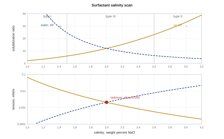
Healy and Reed showed in the 1970s that the interfacial tensions are tied to the solubilization ratios, the volumes of oil and of water dissolved in the microemulsion per volume of surfactant. As salinity rises through the type III window, the oil solubilization ratio rises, the water ratio falls, and they cross at the optimum salinity. Huh's relation of 1979 links the tension to the solubilization ratio:
so a solubilization ratio of 10 or more at optimum salinity gives a tension of 0.003 dyn/cm or less. This makes the simple salinity scan, a row of pipettes containing oil, brine and surfactant at increasing salinity, the workhorse of surfactant design. The laboratory looks for a formulation with a high solubilization ratio at the reservoir's salinity, rapid equilibration, no gels or viscous phases, and stability at reservoir temperature.
# Surfactant phase behavior: a salinity scan, Huh's equation and slug design.
SI = False     # True: metric units, False: oilfield units
BBL = 6.2898
S_opt, SP_opt, C_H = 2.0, 12.0, 0.3        # optimum salinity (wt % NaCl), solubilization at optimum, Huh constant mN/m

def sp_oil(s): return SP_opt * (s / S_opt) ** 2.5     # oil solubilized per volume of surfactant
def sp_wat(s): return SP_opt * (S_opt / s) ** 2.5     # water solubilized per volume of surfactant

U = "mN/m" if SI else "dyn/cm"
print(f" salinity  type   SPo    SPw    IFT o/m   IFT m/w  ({U})")
for s in (1.0, 1.4, 1.7, 2.0, 2.3, 2.7, 3.2):
    so, sw = sp_oil(s), sp_wat(s)
    t = 'I' if s < 0.75 * S_opt else ('II' if s > 1.3 * S_opt else 'III')
    i_om, i_mw = C_H / so ** 2, C_H / sw ** 2
    print(f"  {s:4.1f} %    {t:3s} {so:6.1f} {sw:6.1f}   {i_om:8.4f}  {i_mw:8.4f}")
ift = C_H / SP_opt ** 2
v = 0.30 / 86400; nc = v * 20e-3 / (ift * 1e-3)
print(f"At optimum salinity IFT = {ift:.4f} {U}; with a 20 " + ("mPa·s" if SI else "cp") + f" slug Nc = {nc:.1e}")

# Slug design for one pattern: 0.3 PV of 1 wt % surfactant, retention 0.2 mg/g rock
area, h, phi, rho_r = 16.2e4, 6.5, 0.14, 2650.0
pv = area * h * phi
surf_inj = 0.3 * pv * 1000 * 0.01 / 1000            # metric tons injected
retained = area * h * (1 - phi) * rho_r * 0.2e-6     # metric tons retained (0.2 mg/g) if all rock is contacted
print(f"Pattern PV {pv / 1e3:,.0f} thousand m³" if SI else f"Pattern PV {pv * BBL / 1e6:.2f} million bbl")
print(f"Surfactant injected {surf_inj:,.0f} t; retention capacity {retained:,.0f} t "
f"({retained / surf_inj:.0%} of the slug); alkali to cut retention is worth testing")salinity type SPo SPw IFT o/m IFT m/w (dyn/cm) 1.0 % I 2.1 67.9 0.0667 0.0001 1.4 % I 4.9 29.3 0.0124 0.0004 1.7 % III 8.0 18.0 0.0047 0.0009 2.0 % III 12.0 12.0 0.0021 0.0021 2.3 % III 17.0 8.5 0.0010 0.0042 2.7 % II 25.4 5.7 0.0005 0.0093 3.2 % II 38.9 3.7 0.0002 0.0218 At optimum salinity IFT = 0.0021 dyn/cm; with a 20 cp slug Nc = 3.3e-02 Pattern PV 0.93 million bbl Surfactant injected 442 t; retention capacity 480 t (109% of the slug); alkali to cut retention is worth testing
The model scan finds an optimum at 2 percent salinity with a solubilization ratio of 12 and a tension near 0.002 dyn/cm, and the capillary number of a viscous surfactant slug is around 10⁻², enough to displace nearly all the residual oil the slug contacts. The second part of the output is the sobering one. A slug of 0.3 pore volumes at 1 percent contains about as much surfactant as the rock in the pattern can retain at 0.2 milligrams per gram. If the whole slug is adsorbed before it reaches the producers, the flood fails. Retention is the main economic risk of surfactant flooding, and much of the design effort goes into reducing it.
Designing the flood: salinity gradient and mobility control
A practical chemical flood is a sequence of slugs. A preflush may adjust the reservoir brine. The surfactant slug, typically 0.2 to 0.5 pore volumes, contains surfactant, co-solvent and polymer. It is followed by a polymer drive of 0.5 to 1 pore volume, then water. Two design principles, learned through many failed field tests in the 1970s and 1980s, are now standard. First, the slug must have lower mobility than the oil bank ahead of it, so polymer is added to the slug and the drive; otherwise the slug fingers into the oil bank and is dispersed. Second, the salinity should decline from the reservoir brine through the slug to the drive, a salinity gradient: the reservoir ahead is over-optimum, keeping surfactant in the oil-free brine from being trapped in a type II phase, while the drive behind is under-optimum, so surfactant left behind is remobilized into the water.
Worked problem
Interfacial tension from a salinity scan
A salinity scan at reservoir temperature gives oil and water solubilization ratios that are equal at 2.0 percent NaCl, where each is 12. At 1.7 percent the oil solubilization ratio is 8.0. Use Huh's relation with C = 0.3 dyn/cm to estimate the tension at optimum and the oil-microemulsion tension at 1.7 percent, and find the capillary number at optimum for a slug of viscosity 20 cp moving at 1.0 ft/d.
Show solution
- At optimum, σ = 0.3 / 12² = 0.3 / 144 = 0.0021 dyn/cm.
- At 1.7 percent, σ_om = 0.3 / 8.0² = 0.0047 dyn/cm.
- With v = 3.5 × 10⁻⁶ m/s and μ = 0.020 Pa·s, N_c = 3.5 × 10⁻⁶ × 0.020 / 2.1 × 10⁻⁶ = 3.3 × 10⁻².
Answer: The optimum tension is about 0.002 dyn/cm. Slightly under-optimum the tension doubles but stays ultralow. With a polymer-thickened slug the capillary number is about 3 × 10⁻², high enough to mobilize nearly all residual oil.
Alkaline and ASP flooding
Many crude oils contain naphthenic acids, measured by their total acid number. When an alkali such as sodium carbonate or sodium hydroxide contacts such an oil, it reacts with the acids at the interface to make soap, a natural surfactant generated in place. Alkali also raises the pH, which makes sandstone and clay surfaces more negatively charged and reduces the adsorption of anionic surfactants, often by half or more. Alone, alkaline flooding rarely reaches ultralow tension, but combined with a small amount of synthetic surfactant and with polymer for mobility control it forms the alkaline-surfactant-polymer (ASP) process, in which the soap and the synthetic surfactant work together over a broader salinity window.
ASP flooding has been applied at the largest scale in the Daqing field in China, where it moved from pilots in the 1990s to commercial use. It was also tested in the Minnelusa sands of Wyoming and in Mannville sands near Taber in southern Alberta, among other places. Its drawbacks are operational. Alkali reacts with divalent ions and with clays, precipitating carbonate and silicate scale in producers and pumps; the produced fluids form stable emulsions that are hard to treat; and sodium hydroxide is strongly corrosive. Sodium carbonate, a milder alkali, and water softening upstream of injection reduce but do not remove these problems. Variants include alkali-co-solvent-polymer floods for acidic oils that need no synthetic surfactant at all.
Low-salinity and engineered water
In the 1990s, laboratory work at the University of Wyoming and later by BP showed that injecting water of much lower salinity than the formation brine could recover additional oil from some sandstone cores, sometimes 5 to 15 percent of the oil in place. The effect requires clay minerals in the rock, polar components in the oil and divalent ions in the original brine, and its mechanism is still debated: proposed explanations include multicomponent ion exchange on clay surfaces, expansion of the electrical double layer, release of fines, and a local rise in pH, all of which shift the rock toward more water-wet behavior. Field results have been mixed, with some single-well tests and the Endicott field pilot in Alaska reporting reduced residual oil and other projects showing little effect. In carbonates, so-called smart water or engineered water with adjusted sulfate, calcium and magnesium can change wettability in a similar way. These processes are attractive because they need no chemicals, only a water treatment plant, and they can be combined with polymer, which performs better in low-salinity water.
Ethan's conclusion for the Mission Canyon pool is that a surfactant-polymer flood could in principle reach the residual oil, but the risks are high: retention in a clay-bearing sand, a salinity window that must be held through years of injection, and emulsion handling at the battery. A low-salinity polymer flood is cheaper and less risky but recovers less. Both stay on the list for the capstone.
From laboratory to field
A surfactant formulation that looks good in pipettes must still pass corefloods before it reaches the field. The standard test floods a reservoir core, restored to waterflood residual oil, with the planned slug and polymer drive at reservoir temperature, and measures the oil recovered, the surfactant retained and the pressure drop. A good formulation recovers more than 90 percent of the residual oil in the core, with retention below about 0.2 milligrams per gram and no pressure build-up from viscous phases. Single-well chemical tracer tests in the field then measure residual oil saturation before and after a small surfactant injection around one well, giving a direct check of the laboratory result in the reservoir itself before a multi-pattern pilot is committed.
Common mistakes
MistakeChoosing a surfactant by tension measured in fresh water.
InsteadRun a salinity scan with the reservoir oil and brine at reservoir temperature; optimum salinity governs the tension.
MistakeInjecting a surfactant slug without polymer.
InsteadThe slug must have lower mobility than the oil bank, so polymer is added to the slug and drive.
MistakeIgnoring surfactant retention in slug design.
InsteadRetention can consume the entire slug; measure it in corefloods and reduce it with alkali or sacrificial agents.
MistakeTreating low-salinity water as a universal EOR method.
InsteadIt needs clays, polar oil components and divalent ions in the formation brine, and field results vary.
Summary and key terms
- Surfactants lower oil-water tension; anionic surfactants dominate in sandstones because they adsorb less.
- Winsor type I, III and II systems form as salinity rises; the type III middle phase gives the lowest tensions.
- At optimum salinity the oil and water solubilization ratios are equal, and Huh's relation gives σ = C / SP².
- Chemical floods use a surfactant-polymer slug, a polymer drive and a declining salinity gradient.
- Alkali generates soap from acidic oils and cuts surfactant adsorption; ASP combines alkali, surfactant and polymer but brings scale and emulsions.
- Low-salinity and engineered water can shift wettability and recover extra oil in suitable rock and brine systems.
- Surfactant
- A molecule with hydrophilic and hydrophobic parts that collects at interfaces and lowers their tension.
- Microemulsion
- A thermodynamically stable mixture of oil, water and surfactant.
- Winsor type III
- A three-phase system with a middle-phase microemulsion between excess oil and excess water.
- Optimum salinity
- The salinity at which oil and water solubilization ratios are equal and tensions are lowest.
- Solubilization ratio
- Volume of oil or water in the microemulsion per volume of surfactant.
- ASP flooding
- Alkaline-surfactant-polymer flooding.
- Total acid number
- The milligrams of potassium hydroxide needed to neutralize one gram of oil.
Practice problems
Work each problem on paper first, then reveal the answer to check.
What tension does Huh's relation give for SP = 20?
Show answer
0.3 / 400 = 0.00075 dyn/cm.
Why should the drive be under-optimum in salinity?
Show answer
Surfactant left behind then partitions into the water as type I and is remobilized rather than trapped in oil.
How does alkali reduce surfactant adsorption?
Show answer
Raising pH makes rock surfaces more negatively charged, repelling anionic surfactant.
Name two operational problems of ASP floods.
Show answer
Scale from alkali reacting with divalent ions and clays, and stable produced emulsions.
Lesson quiz · 5 questions
Score 60% or more to complete this lesson.
Create a free account to save your progress, take quizzes and earn a certificate.