
PET-230 · Lesson 9 of 12 · 28 min
Unsteady-flow processes: filling and emptying
Steady flow describes the plant at full load, but some of the most important events at Northgate are not steady at all. Every few minutes the air compressor starts, charges the instrument-air receiver from its low setpoint to its high setpoint, and stops. Each autumn, the cold district main is warmed and filled with steam. The boiler drum is filled with water before firing, and blown down to remove sludge. A relief valve opens and a vessel empties. In each case, the mass and energy inside the control volume change with time. This lesson extends the control-volume balances to such transient, or unsteady-flow, processes.
The general balances
Lesson 7 gave the mass and energy balances for a control volume in rate form. Integrating them over the duration of a process, from an initial state 1 to a final state 2, gives
where \(\theta = h + V^2/2 + gz\) is the energy carried per unit mass by each stream. In general the properties of the entering and leaving streams can change during the process, and so can the state inside the control volume, which makes the integrals hard to evaluate. Two idealizations make most practical problems tractable.
The uniform-flow model
In a uniform-flow process, the properties of each stream crossing the boundary are constant in time and uniform over the inlet or outlet area, although the flow rates may vary; and the state inside the control volume, while it changes with time, is uniform throughout at any instant. A tank filled from a large supply line meets the first condition well, because the line pressure and temperature hardly change; the second condition holds approximately if the gas inside mixes well. With these assumptions the integrals become simple products, and with kinetic and potential energies neglected, the energy balance becomes
Note carefully: the streams carry enthalpy \(h\), because they do flow work as they cross the boundary, while the contents of the control volume store internal energy \(u\). This asymmetry is the source of most of the interesting results in transient problems, and of most of the mistakes.
Worked problem
Filling an evacuated tank
A rigid tank is initially evacuated. A valve connects it to a supply line carrying air at a steady 20 °C. The valve is opened, air flows in until the tank pressure equals the line pressure, and the valve is closed. If the process is fast enough to be adiabatic, what is the final temperature of the air in the tank?
Show solution
- Control volume: the tank. Uniform flow, one inlet, no exit, no work, adiabatic, \(m_1 = 0\).
- Mass: \(m_{\text{in}} = m_2\). Energy: \(m_{\text{in}}h_{\text{line}} = m_2u_2\), so \(u_2 = h_{\text{line}}\).
- For an ideal gas with constant specific heats, measuring \(u\) and \(h\) from absolute zero: \(c_vT_2 = c_pT_{\text{line}}\), so \(T_2 = kT_{\text{line}}\).
- \[T_2 = 1.4(293.15) = 410\ \text{K} = 137\ °\text{C}\]
Answer: The air in the tank ends up 117 °C hotter than the air in the line, even though no heat was added. The temperature rise comes from flow work: the line air pushes each parcel into the tank, and that work becomes internal energy of the tank's contents. In practice heat transfer to the tank walls reduces the rise, but anyone who has felt a bicycle pump barrel or a freshly filled scuba tank grow warm has seen this effect.
The result does not depend on the line pressure or the size of the tank. That is a hallmark of uniform-flow problems: often the answer comes out in terms of properties alone, once the mass and energy balances are combined.
Charging the instrument-air receiver
The Northgate receiver is never evacuated; it cycles between about 600 and 900 kPa absolute. Each time the compressor starts, warm air from the aftercooler flows in and compresses the air already in the tank. The temperature rises during charging and then falls slowly as the tank loses heat to the compressor room, so the pressure sags a little after the compressor stops. Graham had noticed this sag and wondered whether the check valve was leaking.
Worked problem
Temperature rise during charging
The 2.0 m³ (70.6 ft³) receiver holds air at 600 kPa (87 psia) and 20 °C (68 °F) when the compressor starts. Air arrives from the aftercooler at 40 °C (104 °F), and charging stops at 900 kPa (130.5 psia). Assuming adiabatic charging, find the final temperature, the mass of air added, and the pressure after the tank cools back to 20 °C. Use \(c_p = 1.005\), \(c_v = 0.718\ \text{kJ/(kg·K)}\).
Show solution
- Initial mass: \(m_1 = P_1V/(RT_1) = 600(2.0)/(0.287 \times 293.15) = 14.26\ \text{kg}\).
- Mass balance: \(m_{\text{in}} = m_2 - m_1\). Energy balance (adiabatic, no work): \(m_{\text{in}}c_pT_{\text{in}} = m_2c_vT_2 - m_1c_vT_1\).
- Since \(m_2T_2 = P_2V/R = 6272\ \text{kg·K}\) is known, substitute \(m_2 = 6272/T_2\): \((6272/T_2 - 14.26)(1.005)(313.15) = 0.718(6272) - 14.26(0.718)(293.15)\).
- The right side is \(4503 - 3001 = 1502\ \text{kJ}\). Then \(6272/T_2 - 14.26 = 1502/314.7 = 4.77\), so \(m_2 = 19.03\ \text{kg}\) and \(T_2 = 6272/19.03 = 329.6\ \text{K} = 56.4\ °\text{C}\).
- After cooling at constant volume and mass: \(P_3 = P_2(T_1/T_2) = 900(293.15/329.6) = 801\ \text{kPa}\).
Answer: The air in the tank reaches about 56 °C, and as it cools the pressure falls from 900 to about 800 kPa with no leak at all. Graham's sag was thermodynamics, not a faulty check valve. A receiver sized on the assumption that the pressure stays at 900 kPa will deliver less air between compressor starts than expected.
The program below repeats this calculation and then simulates the charging step by step, allowing heat to flow from the warming air to the tank wall and the room. In each small time step it adds the energy brought in by the entering air, subtracts the heat lost, and recomputes the temperature from the new internal energy and mass. It finishes with the evacuated-tank result.
# Charging the 2.0 m3 instrument-air receiver from 600 kPa to 900 kPa (absolute)
R, cp = 0.287, 1.005
cv = cp - R
V, P1, T1 = 2.0, 600.0, 293.15          # m3, kPa, K (tank starts at room temperature)
P2, T_in = 900.0, 313.15                # target pressure; air arrives at 40 C from the aftercooler
m1 = P1 * V / (R * T1)

# 1. Adiabatic, uniform flow: (m2 - m1) cp T_in = m2 cv T2 - m1 cv T1, with m2 = P2 V / (R T2)
#    -> cv P2 V / R - m1 cv T1 = cp T_in (P2 V / (R T2) - m1), solve for T2
T2 = cp * T_in * P2 * V / R / (cv * P2 * V / R - m1 * cv * T1 + cp * T_in * m1)
m2 = P2 * V / (R * T2)
print(f"adiabatic: m1 = {m1:.2f} kg, m2 = {m2:.2f} kg, added {m2 - m1:.2f} kg, T2 = {T2 - 273.15:.1f} C")
print(f"after cooling to 20 C the pressure settles at {m2 * R * T1 / V:.0f} kPa")

# 2. Time-stepping with heat loss to the tank wall and room: Q_out = UA (T - T_room)
mdot, UA, T_room = 0.12, 0.060, 293.15  # kg/s, kW/K, K
m, T, t, dt = m1, T1, 0.0, 0.1
while m * R * T / V < P2:
    Q_out = UA * (T - T_room)
    U = m * cv * T + (mdot * cp * T_in - Q_out) * dt   # energy balance over dt
    m += mdot * dt
    T = U / (m * cv)
    t += dt
print(f"with heat loss: reaches {P2:.0f} kPa after {t:.0f} s, T = {T - 273.15:.1f} C, m = {m:.2f} kg")

# 3. Filling an evacuated rigid tank from a supply line: T2 = k T_line (adiabatic)
k = cp / cv
print(f"evacuated tank filled from a 20 C line: T2 = {k * 293.15 - 273.15:.1f} C")adiabatic: m1 = 14.26 kg, m2 = 19.03 kg, added 4.77 kg, T2 = 56.4 C after cooling to 20 C the pressure settles at 801 kPa with heat loss: reaches 900 kPa after 41 s, T = 53.8 C, m = 19.18 kg evacuated tank filled from a 20 C line: T2 = 137.2 C
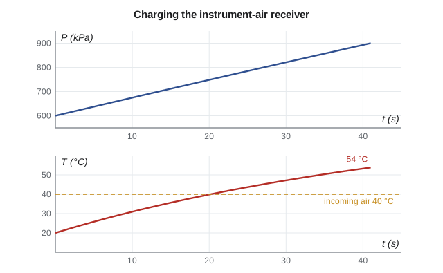
With a modest wall heat loss the final temperature is 53.8 °C rather than 56.4 °C, and slightly more air goes in before the pressure switch trips. The adiabatic calculation is a good first estimate, and the simulation shows how to refine it once heat transfer can be estimated. Note also that the tank air ends up hotter than the 40 °C air entering it: flow work again.
Filling with steam
The same balances apply to steam, with properties from the tables instead of the ideal-gas relations. Each autumn, before the heating season, a section of the district main is isolated, drained, and then refilled with steam. The first steam into the cold, empty pipe condenses on the walls, which is why warming is done slowly through a small bypass valve with the drains open. But consider an idealized version: an insulated, evacuated vessel filled from the main.
Worked problem
An evacuated vessel filled from the steam main
An insulated, rigid vessel, initially evacuated, is connected to the main carrying steam at 1 MPa and 250 °C (\(h = 2943.1\ \text{kJ/kg}\)). The valve is opened until the vessel reaches 1 MPa. Find the final temperature. At 1 MPa: \(u = 2875.7\ \text{kJ/kg}\) at 350 °C and 2957.9 kJ/kg at 400 °C.
Show solution
- As for the evacuated air tank: \(u_2 = h_{\text{line}} = 2943.1\ \text{kJ/kg}\), at \(P_2 = 1\ \text{MPa}\).
- Since 2943.1 lies between the internal energies at 350 °C and 400 °C, interpolate: \(T_2 = 350 + 50(2943.1 - 2875.7)/(2957.9 - 2875.7) = 350 + 41.0 = 391\ °\text{C}\).
Answer: The steam in the vessel ends up at about 391 °C, 141 °C hotter than the steam in the main, for the same reason as the air. The internal energies were found from the table as \(u = h - Pv\): at 350 °C, \(3158.2 - 1000(0.28250) = 2875.7\ \text{kJ/kg}\).
Emptying and blowdown
When mass leaves a control volume during a transient, the exit stream's enthalpy usually changes as the contents change, and the uniform-flow assumption for the exit must be applied with care. For a tank discharging gas, the gas remaining inside expands as the tank empties and cools, so the exit enthalpy falls. If the process is slow and the remaining gas expands reversibly and adiabatically, its temperature follows the isentropic relation of Lesson 11; otherwise, an average exit enthalpy is used, or the process is integrated step by step as in the program.
Boiler blowdown is a liquid example. A small fraction of the boiler water, carrying concentrated dissolved solids, is discharged continuously or in bursts to keep the water chemistry within limits. The blowdown water leaves as saturated liquid at boiler pressure, and when it is throttled to atmospheric pressure, part of it flashes into steam. Many plants, including Northgate, pass blowdown through a flash tank to recover that steam for the deaerator, and then through a heat exchanger to recover energy from the remaining hot water.
Worked problem
Flash steam from blowdown
Boiler blowdown leaves as saturated liquid at 4 MPa (\(h_f = 1087.3\ \text{kJ/kg}\)) at 0.30 kg/s and is throttled into a flash tank at 120 kPa (\(h_f = 439.4\), \(h_{fg} = 2243.7\ \text{kJ/kg}\)). What steam flow can be recovered?
Show solution
- Throttling: \(h\) is unchanged, so the mixture entering the flash tank has \(h = 1087.3\ \text{kJ/kg}\) at 120 kPa.
- Quality: \(x = (1087.3 - 439.4)/2243.7 = 0.289\). Steam recovered: \(0.289(0.30) = 0.087\ \text{kg/s}\).
Answer: About 29 percent of the blowdown flashes to steam that can go straight into the deaerator, saving roughly 0.087 kg/s of steam from the main. The flash tank itself operates in steady flow; the transient element is that blowdown is often intermittent, which is why the tank is sized for the peak flow.
Choosing between steady and unsteady analysis
The same device can call for different models at different times. A boiler at constant load is a steady-flow device; the same boiler during a cold start, when its contents are heating up and its water level is changing, is not. The test is whether the mass and energy inside the control volume change significantly during the period of interest. If they do, use the transient balances; if they change only slightly compared with the flows through the device, steady flow is a good approximation even when conditions are drifting slowly. For the receiver, which doubles its mass in under a minute, the transient analysis is essential; for the boiler at full load, steady flow is fine.
Common mistakes
MistakeUsing u for the entering stream in a filling problem.
InsteadEntering and leaving streams carry h; the contents store u.
MistakeAssuming the tank ends at the line temperature.
InsteadFlow work raises the temperature of the contents above the line temperature.
MistakeUsing the steady-flow equation for a tank being filled.
InsteadMass and energy inside change; use m₂u₂ − m₁u₁ on the right-hand side.
MistakeForgetting the initial contents of a partly full tank.
InsteadInclude m₁u₁; only an evacuated tank has m₁ = 0.
MistakeTreating a pressure drop after charging as a leak.
InsteadCheck whether cooling at constant volume explains it before hunting for leaks.
Summary and key terms
- Transient processes change the mass and energy inside a control volume over time.
- Mass: m_in − m_out = m₂ − m₁.
- Uniform flow, negligible KE and PE: Q − W + Σm_in h_in − Σm_out h_out = m₂u₂ − m₁u₁.
- Streams carry enthalpy; contents store internal energy.
- Filling an evacuated tank adiabatically from a line gives u₂ = h_line, and T₂ = kT_line for an ideal gas.
- Step-by-step simulation handles heat transfer and changing exit conditions.
- Throttled saturated liquid partly flashes to vapor, which can be recovered.
- Unsteady-flow process
- A process in which the mass or energy inside a control volume changes with time.
- Transient process
- Another name for an unsteady-flow process.
- Uniform-flow process
- A transient process with stream properties constant in time and contents uniform at each instant.
- Charging
- Filling a vessel with fluid from a supply.
- Discharging
- Emptying a vessel through an outlet.
- Blowdown
- Removal of boiler water to control dissolved solids.
- Flash steam
- Vapor formed when saturated liquid is throttled to a lower pressure.
Practice problems
Work each problem on paper first, then reveal the answer to check.
An evacuated tank is filled from a helium line at 25 °C (k = 1.667). Find the final temperature if adiabatic.
Show answer
About 224 °C (497 K).
A 1 m³ tank of air at 100 kPa and 20 °C is filled adiabatically from a 20 °C line to 500 kPa. Find T₂.
Show answer
About 380 K (107 °C).
In the previous problem, what mass enters?
Show answer
About 3.40 kg.
Saturated liquid at 1 MPa (h_f = 762.5) is throttled to 100 kPa (h_f = 417.5, h_fg = 2257.5). What fraction flashes?
Show answer
0.153.
Why does a receiver's pressure fall after the compressor stops even with no air drawn?
Show answer
The hot charged air cools at constant volume, so its pressure drops.
In the program, set UA to 0.20 kW/K. How do the final temperature and charging time change?
Show answer
The final temperature falls to about 48 °C and charging takes about 44 s.
Lesson quiz · 5 questions
Score 60% or more to complete this lesson.
Create a free account to save your progress, take quizzes and earn a certificate.