
MEC-450 · Lesson 9 of 12 · 21 min
Solids, shells and practical model building
The casing cover of the heavier-duty TP-80 is the part Farah worries about most. The mining customer wants the pump hydrostatically tested at a higher pressure than the standard model, and the cover is a ribbed casting held by eight 1/2-13 UNC grade 5 bolts, each preloaded to 9.05 kip, sealed by a gasket in a groove, and pierced by a tapping for a pressure gauge. No handbook formula describes it. It is a genuinely three-dimensional part, and this lesson follows Owen as he plans its model: which elements to use, how much of the cover to model, how to represent the bolts and the gasket, and how to bound the answer before he trusts it. Most of an analyst's time on a real part goes into decisions like these rather than into the solver.
Solid elements
Three-dimensional solids are meshed with tetrahedra or hexahedra (bricks), each node carrying three displacements. Everything from Lessons 5 to 7 carries over: shape functions, isoparametric mapping, Gauss quadrature, B and D matrices. The linear four-node tetrahedron is a constant-strain element with the CST's stiffness in bending, and should be used only in fine meshes or where accuracy matters little. The ten-node quadratic tetrahedron is the workhorse of mechanical analysis, because automatic meshers can fill any geometry with tetrahedra and the quadratic version represents bending and stress gradients well. Twenty-node and eight-node bricks are more efficient per degree of freedom but need geometry that can be swept or mapped, which castings with fillets and bosses rarely allow without significant effort.
A practical consequence is model size. A fine quadratic tetrahedral mesh of a part like the cover can easily reach a quarter of a million elements, with roughly 1.4 nodes per element and three degrees of freedom per node: about a million equations. Modern solvers handle that in minutes on a workstation, but each additional load case, contact iteration or design change multiplies the time, and very large models are hard to check. Reducing the model by symmetry, by idealizing thin regions as shells or by removing features that do not matter is still worthwhile.
Shell elements
Thin-walled parts, such as fabricated baseplates, sheet-metal guards, tanks and the webs of channels, are poorly suited to solid elements: several quadratic solids are needed through the thickness to capture bending, and the elements become flat and badly shaped. Shell elements represent the wall by its mid-surface, with five or six degrees of freedom per node (three displacements and two or three rotations), and include bending through the thickness analytically, just as beam elements include bending through the depth. A rule of thumb is that walls thinner than about a tenth of their span are good candidates for shells. The heavier-duty baseplate, made of 10 mm plate spanning 600 mm, is modeled with shells; the cover, whose thickness is a fifth of its diameter and which has ribs, bosses and a groove, is modeled with solids.
Shell models need care at junctions. Mid-surfaces of plates welded at right angles meet at a line that is not where the material is, so the model has slightly too much or too little material at every joint, and weld stresses are not represented at all. Owen's practice for the baseplate is to read stresses half a plate thickness or more from each junction, following the hot-spot stress approaches used in welded fatigue assessment, and to model a critical weld in solids if its stress governs the design.
Symmetry
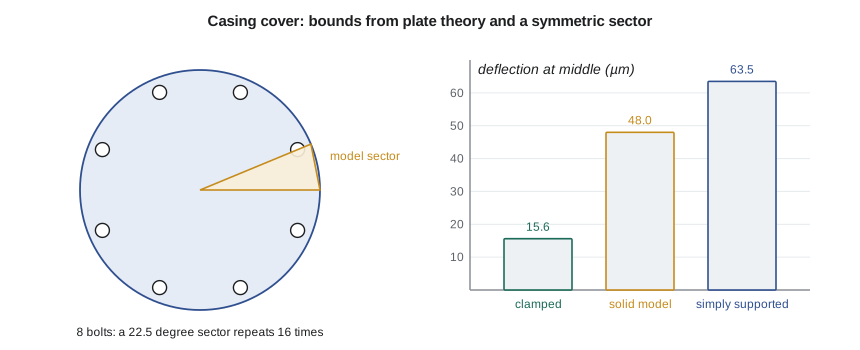
Symmetry is the most effective way to reduce a model. If geometry, material, supports and loads are all symmetric about a plane, only half the part needs to be modeled, with displacement perpendicular to the plane set to zero on the cut face and the in-plane displacements left free. Two planes give a quarter model. A part with repeated sectors, like the cover with its eight equally spaced bolts, can be reduced to a single sector if its features repeat exactly and the load is the same on every sector; for internal pressure that is true. The cover's eight bolts and the symmetry plane through each bolt and midway between bolts make a 22.5 degree sector, one sixteenth of the cover.
Symmetry has a trap: it constrains the solution to be symmetric. That is correct for static stress under symmetric loads but wrong for vibration, where many modes are antisymmetric, and for buckling. A modal analysis of a half model with symmetric boundary conditions finds only the symmetric modes, and a missed antisymmetric mode could be the one that resonates. For the cover's stress analysis the sector model is correct; for a modal check it would not be.
Bolts, gaskets and contact
The bolts and gasket are where the cover analysis becomes difficult. A cover bolted to a casing is not clamped at its edge, and it is not simply supported: the bolts are preloaded, the gasket compresses, and under pressure the cover lifts slightly at the gasket, pivoting on the region outside the bolt circle where the flanges touch. Capturing that needs contact, a nonlinear boundary condition in which surfaces can separate and press together but not pass through each other, usually with friction. Contact makes the analysis iterative and slower, and its results depend on settings such as contact stiffness and friction coefficient that should be tested for sensitivity.
Bolts can be modeled in increasing detail. A coupling or beam element joining the bolt head area to the threaded region, with a preload applied as an initial shortening, is enough for the cover's stiffness and the joint's separation. A solid bolt with modeled threads is needed only when the bolt's own stresses are the subject. The gasket is usually modeled with special gasket elements whose thickness-direction behavior follows the manufacturer's nonlinear compression curve, while their in-plane stiffness is negligible. Owen begins with the simplest model that captures joint opening: beam bolts, preloaded, and frictional contact between the flanges, with the gasket represented by its compression curve.
Bounding the answer
Before running the contact model, Owen bounds its answer with plate theory, the same habit of independent estimates that Lesson 1 started. A flat circular plate of the cover's thickness, 22 mm, with a radius equal to the bolt circle, 105 mm, under the 16 bar design pressure gives two limiting cases from Roark-type formulas: a fully clamped edge, too stiff, and a simply supported edge, too flexible. The real cover, with ribs that stiffen it and a bolted edge that is neither, should lie between them, and if a model says otherwise, something is wrong.
# Building a 3D model of the TP-80 casing cover: bounding the answer with plate theory, symmetry and model size
import math
E, nu = 200e9, 0.3                      # cast steel cover (Pa)
p = 1.6e6                               # 16 bar design pressure, Pa
a = 0.105                               # radius to the bolt circle, m
t = 0.022                               # cover thickness, m
Dp = E * t**3 / (12 * (1 - nu**2))      # plate flexural rigidity, N m
w_cl = p * a**4 / (64 * Dp)
w_ss = (5 + nu) / (1 + nu) * p * a**4 / (64 * Dp)
s_cl = 3 * p * a**2 / (4 * t**2)                   # clamped: radial stress at the edge
s_ss = 3 * (3 + nu) * p * a**2 / (8 * t**2)        # simply supported: stress at the center
print(f"Flexural rigidity D = {Dp/1e3:.1f} kN m")
print(f"Center deflection: clamped edge {1e6*w_cl:.1f} um, simply supported edge {1e6*w_ss:.1f} um")
print(f"Largest bending stress: clamped (at the edge) {s_cl/1e6:.1f} MPa, simply supported (at the center) {s_ss/1e6:.1f} MPa")
w_fe, s_fe = 48.0e-6, 41.5e6            # Owen's solid model with bolt preload and frictional contact at the gasket face
print(f"Solid model: center deflection {1e6*w_fe:.1f} um, largest bending stress away from the bolt holes {s_fe/1e6:.1f} MPa")
f = (w_fe - w_cl) / (w_ss - w_cl)
print(f"The model's deflection lies {100*f:.0f} percent of the way from the clamped to the simply supported bound: plausible")
# Model size: second-order tetrahedra with about 1.4 nodes per element in a large mesh, 3 DOF per node
for name, frac in (("full cover", 1.0), ("half (one plane of symmetry)", 0.5), ("1/16 sector (8 bolts, symmetric)", 1/16)):
    elems = 260_000 * frac; nodesn = 1.4 * elems; dofs = 3 * nodesn
    print(f"{name:34s}: about {elems:9,.0f} elements, {dofs:10,.0f} DOF")
# Bolt preload converted to an equivalent uniform clamp pressure on the gasket ring
for site, F, n in (("ca: 8 x M12 class 8.8", 36.7e3, 8), ("us: 8 x 1/2-13 UNC grade 5", 9.05 * 4448.2, 8)):
    ring = math.pi * (0.096**2 - 0.084**2)
    print(f"{site}: total preload {n*F/1e3:.0f} kN, gasket ring {ring*1e4:.1f} cm^2, mean clamp {n*F/ring/1e6:.1f} MPa;"
f" pressure end load {p*math.pi*0.090**2/1e3:.1f} kN")Flexural rigidity D = 195.0 kN m Center deflection: clamped edge 15.6 um, simply supported edge 63.5 um Largest bending stress: clamped (at the edge) 27.3 MPa, simply supported (at the center) 45.1 MPa Solid model: center deflection 48.0 um, largest bending stress away from the bolt holes 41.5 MPa The model's deflection lies 68 percent of the way from the clamped to the simply supported bound: plausible full cover : about 260,000 elements, 1,092,000 DOF half (one plane of symmetry) : about 130,000 elements, 546,000 DOF 1/16 sector (8 bolts, symmetric) : about 16,250 elements, 68,250 DOF ca: 8 x M12 class 8.8: total preload 294 kN, gasket ring 67.9 cm^2, mean clamp 43.3 MPa; pressure end load 40.7 kN us: 8 x 1/2-13 UNC grade 5: total preload 322 kN, gasket ring 67.9 cm^2, mean clamp 47.5 MPa; pressure end load 40.7 kN
The bounds are 15.6 µm (clamped) and 63.5 µm (simply supported) for the center deflection, and 27.3 MPa and 45.1 MPa for the largest bending stress. Owen's sector model, with preloaded bolts and contact, gives 48.0 µm and 41.5 MPa away from the bolt holes. Both lie inside the bounds, about two thirds of the way toward the simply supported case, which is what a bolted edge with a gasket should look like. The model also shows higher local stresses at the bolt holes and the gauge tapping, which plate theory cannot predict and which will be assessed separately against the casting's fatigue strength.
The program also shows why symmetry matters: a full quadratic tetrahedral model of about 260,000 elements has around a million degrees of freedom, while the one-sixteenth sector has about 68,000, small enough to run in seconds and to repeat for the sensitivity studies that contact demands. Finally, the program compares the total bolt preload, about 294 kN on the Canadian site's metric bolts and 322 kN on the US site's inch bolts, with the pressure end load of about 41 kN on the gasket's mean diameter. The preload is seven to eight times the pressure load, so the joint should stay closed with a large margin at the design pressure; the model confirms that the gasket stays compressed, which is the real purpose of the analysis.
Worked problem
Is a half model enough for the cover's modal check?
The customer also asks whether the cover has a natural frequency near the pump's 176 Hz vane-pass frequency. Owen considers reusing the one-sixteenth sector model. Is it suitable?
Show solution
- Pressure loading is the same on every sector, so the static sector model is valid.
- Natural modes of a plate include patterns with one, two or more nodal diameters, which are not symmetric about every sector plane.
- A sector model with symmetric boundary conditions captures only the axisymmetric family of modes.
- A full model, or a cyclic-symmetry analysis that most packages offer, is needed to find all modes.
Answer: No. The sector model is valid for pressure stress but would miss most of the cover's modes. Owen runs the modal check on the full model with bolted contact replaced by its linearized stiffness.
Defeaturing and the model plan
Small features that do not affect the result of interest, such as cosmetic chamfers, logos and small fillets far from the region of interest, can be removed before meshing, a process called defeaturing. It makes meshing easier and the model smaller. The judgment is in deciding which features are small: a 1 mm fillet at a highly stressed rib root matters a great deal, while the same fillet on an unstressed boss does not. Owen writes a short model plan before building any model: the question to be answered, the idealization, the elements, the symmetry, the boundary conditions, the loads and how they are applied, the results to be extracted and the independent checks. Farah reviews the plan before the model is built, which catches more errors than reviewing the results afterward.
Common mistakes
MistakeMeshing a thin fabricated plate with one layer of linear solid elements.
InsteadUse shell elements, or several quadratic solids through the thickness.
MistakeUsing a symmetric sector model for a modal analysis.
InsteadSymmetric boundary conditions miss antisymmetric modes; use the full model or cyclic symmetry.
MistakeModeling a bolted cover as clamped at its edge.
InsteadRepresent bolt preload and contact, or at least bound the answer between clamped and simply supported.
MistakeRemoving a fillet at a highly stressed location during defeaturing.
InsteadKeep features in regions where results are read; remove only those far from them.
MistakeBuilding a large model before deciding what it must answer.
InsteadWrite a model plan and have it reviewed before meshing.
Summary and key terms
- Quadratic tetrahedra are the usual choice for castings; bricks are more efficient where geometry allows; shells suit thin walls.
- Symmetry reduces a model; the cover's sixteenth sector cuts about a million degrees of freedom to about 68,000.
- Symmetric models are wrong for modal and buckling analyzes that need antisymmetric modes.
- Bolted joints need preload and contact; gaskets need their compression behavior.
- Plate theory bounds the cover's deflection at 15.6 and 63.5 µm; the solid model's 48.0 µm lies between them.
- The bolt preload is seven to eight times the pressure load, so the joint stays closed.
- Tetrahedral element
- A four-faced solid element, linear with four nodes or quadratic with ten.
- Hexahedral element
- A six-faced brick element, linear with eight nodes or quadratic with twenty.
- Shell element
- An element representing a thin wall by its mid-surface, with bending through the thickness built in.
- Symmetry boundary condition
- Zero displacement normal to a plane of symmetry.
- Cyclic symmetry
- A method that analyzes one repeated sector while capturing all modes of the full part.
- Contact
- A nonlinear condition allowing surfaces to touch and separate but not interpenetrate.
- Bolt preload
- The tension in a bolt from tightening, applied in models as an initial shortening.
- Gasket element
- An element following a gasket's nonlinear compression curve through its thickness.
- Defeaturing
- Removing small geometric features that do not affect the results of interest.
- Model plan
- A written statement of the question, idealization, elements, loads and checks before a model is built.
Practice problems
Work each problem on paper first, then reveal the answer to check.
A part is symmetric about two perpendicular planes. What fraction must be modeled for a static symmetric load?
Show answer
One quarter.
For the cover, where does the solid model's deflection lie relative to the bounds?
Show answer
48.0 µm, between 15.6 (clamped) and 63.5 µm (simply supported), about 68 percent of the way.
Roughly how many degrees of freedom does a 130,000-element quadratic tetrahedral mesh have?
Show answer
About 3 × 1.4 × 130,000 ≈ 546,000.
Why is contact analysis iterative?
Show answer
Whether surfaces touch or separate depends on the solution, so it is found by repeated solves.
Give two features that could be removed when defeaturing the cover, and one that must stay.
Show answer
Remove cosmetic chamfers and lettering; keep the fillets at the rib roots near the bolt holes.
Lesson quiz · 5 questions
Score 60% or more to complete this lesson.
Create a free account to save your progress, take quizzes and earn a certificate.