
MEC-450 · Lesson 6 of 12 · 21 min
Two-dimensional elements: the constant-strain triangle
Many machine parts are plates loaded in their own plane: a gusset in a baseplate, a flat bracket, a flange seen edge-on, a gear tooth. Others are long prisms with the same cross-section along their length, like a keyway region in a shaft or a dam, or bodies of revolution, like a casing or the shaft shoulder itself. Each can be analyzed as a two-dimensional problem, far cheaper than a full three-dimensional one, if the idealization is chosen correctly. This lesson introduces two-dimensional elasticity and the simplest element for it, the three-node constant-strain triangle, or CST. It is rarely the best element for real work, but it is the easiest to understand, and its weaknesses teach as much as its strengths.
Plane stress, plane strain and axisymmetry
A thin plate loaded in its plane has negligible stress through its thickness: \(\sigma_z = \tau_{xz} = \tau_{yz} = 0\). That is plane stress, and it applies to brackets, gussets and webs. A long body whose cross-section and loads do not change along its length, and whose ends are restrained, has negligible strain along its length: \(\varepsilon_z = 0\). That is plane strain, and it applies to dams, long pipes under external pressure and the region near the middle of a long shaft key. A solid of revolution loaded symmetrically about its axis, such as a pressure vessel, flange or shaft shoulder, is axisymmetric: the problem reduces to a half cross-section with radial and axial displacements, and the hoop strain follows from the radial displacement. Choosing the right one of the three is part of idealization, and an error here changes stresses by tens of percent.
In all three cases each node has two displacements, u and v, and the strain vector has three in-plane components, \(\varepsilon_x = \partial u/\partial x\), \(\varepsilon_y = \partial v/\partial y\) and \(\gamma_{xy} = \partial u/\partial y + \partial v/\partial x\) (axisymmetry adds the hoop strain u/r). The material matrix D relates them to the stresses. For plane stress
while for plane strain the leading terms become \(E(1 - \nu)/((1 + \nu)(1 - 2\nu))\). For steel with ν = 0.3, the program shows the plane strain value is about 22 percent larger, so a plane strain model of a thin bracket would be noticeably too stiff. As ν approaches 0.5, as it does for rubber, the plane strain matrix becomes infinite, a sign of the difficulty of analyzing nearly incompressible materials with simple elements.
The constant-strain triangle
The CST has a node at each corner and assumes that u and v vary linearly over the triangle. The shape functions are the triangle's area coordinates: \(N_i\) equals one at node i, zero at the other two and varies linearly in between. Since linear functions have constant derivatives, the strain is constant everywhere in the element, which gives the element its name. The strain-displacement matrix B depends only on the nodal coordinates:
with \(b_1 = y_2 - y_3\), \(c_1 = x_3 - x_2\) and the others by cycling the indices, and A the triangle's area. Because B and D are constant, the integral \(k = \int B^{\mathsf{T}}DB\,dV\) from Lesson 5 is simply \(tA\,B^{\mathsf{T}}DB\), a 6 by 6 matrix. The element was among the first used in the 1950s and 1960s, and it remains valuable as a teaching tool and in automatic meshers, which fill awkward regions with triangles more easily than with quadrilaterals.
A cantilever plate test
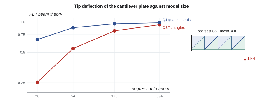
Before using triangles on any TP-80 part, Owen tests them on a problem with a known answer: a steel plate 200 mm long, 50 mm deep and 10 mm thick, clamped along one short edge and carrying 1 kN shared over the other. It is the shape of the motor bracket's gusset, simplified. Beam theory, including the small shear deflection, gives a tip deflection of 0.1342 mm and a bending stress of 48.0 MPa at the clamped root. The program meshes the plate with right triangles, two per rectangle, in four meshes from 4 × 1 rectangles to 32 × 8.
# Constant-strain triangles: a 200 mm x 50 mm steel cantilever plate, 10 mm thick, with 1 kN shared over its free end
def solve(A, b):
    n = len(b); A = [r[:] for r in A]; b = b[:]
    for k in range(n):
        p = max(range(k, n), key=lambda i: abs(A[i][k])); A[k], A[p] = A[p], A[k]; b[k], b[p] = b[p], b[k]
        piv = A[k][k]
        for i in range(k + 1, n):
            f = A[i][k] / piv
            if f:
                rk, ri = A[k], A[i]
                for j in range(k, n): ri[j] -= f * rk[j]
                b[i] -= f * b[k]
    x = [0.0] * n
    for i in range(n - 1, -1, -1): x[i] = (b[i] - sum(A[i][j] * x[j] for j in range(i + 1, n))) / A[i][i]
    return x
E, nu, t = 200e3, 0.3, 10.0                                    # N/mm^2 (MPa), mm
Lx, Hy, P = 200.0, 50.0, 1000.0                                 # mm, mm, N
D = [[E/(1-nu*nu), E*nu/(1-nu*nu), 0], [E*nu/(1-nu*nu), E/(1-nu*nu), 0], [0, 0, E/(2*(1+nu))]]   # plane stress
def cst(xy):
    (x1, y1), (x2, y2), (x3, y3) = xy
    A2 = (x2 - x1) * (y3 - y1) - (x3 - x1) * (y2 - y1)
    b = [y2 - y3, y3 - y1, y1 - y2]; c = [x3 - x2, x1 - x3, x2 - x1]
    B = [[0.0] * 6 for _ in range(3)]
    for i in range(3):
        B[0][2*i] = b[i] / A2; B[1][2*i+1] = c[i] / A2; B[2][2*i] = c[i] / A2; B[2][2*i+1] = b[i] / A2
    DB = [[sum(D[r][k] * B[k][j] for k in range(3)) for j in range(6)] for r in range(3)]
    ke = [[t * A2 / 2 * sum(B[k][i] * DB[k][j] for k in range(3)) for j in range(6)] for i in range(6)]
    return ke, B
def run(nx, ny):
    nid = lambda i, j: j * (nx + 1) + i
    xy = [(i * Lx / nx, j * Hy / ny) for j in range(ny + 1) for i in range(nx + 1)]
    tris = []
    for j in range(ny):
        for i in range(nx):
            a, b, c, d = nid(i, j), nid(i+1, j), nid(i+1, j+1), nid(i, j+1)
            tris += [(a, b, c), (a, c, d)]
    N = 2 * len(xy); K = [[0.0] * N for _ in range(N)]
    for tr in tris:
        ke, _ = cst([xy[k] for k in tr]); idx = [2*k + m for k in tr for m in (0, 1)]
        for p in range(6):
            for q in range(6): K[idx[p]][idx[q]] += ke[p][q]
    F = [0.0] * N
    for j in range(ny + 1):                                   # end load shared along the free edge (trapezoid rule)
        F[2*nid(nx, j) + 1] -= P / ny * (0.5 if j in (0, ny) else 1.0)
    fixed = {2*nid(0, j) + m for j in range(ny + 1) for m in (0, 1)}
    free = [k for k in range(N) if k not in fixed]
    uf = solve([[K[a][b] for b in free] for a in free], [F[a] for a in free])
    u = [0.0] * N
    for k, v in zip(free, uf): u[k] = v
    tip = sum(u[2*nid(nx, j) + 1] for j in range(ny + 1)) / (ny + 1)
    smax = 0.0
    for tr in tris:
        _, B = cst([xy[k] for k in tr]); ue = [u[2*k + m] for k in tr for m in (0, 1)]
        eps = [sum(B[r][k] * ue[k] for k in range(6)) for r in range(3)]
        sx = sum(D[0][k] * eps[k] for k in range(3)); smax = max(smax, abs(sx))
    return tip, smax, N
I = t * Hy**3 / 12; G = E / (2 * (1 + nu))
tip_beam = P * Lx**3 / (3 * E * I) + P * Lx / (5/6 * G * t * Hy)
s_beam = P * Lx * (Hy / 2) / I
print(f"Beam theory (bending + shear): tip deflection {tip_beam:.4f} mm, root bending stress {s_beam:.1f} MPa")
print(" mesh     DOF   tip deflection (mm)  ratio to beam   largest element sx (MPa)")
for nx, ny in ((4, 1), (8, 2), (16, 4), (32, 8)):
    tip, sm, N = run(nx, ny)
    print(f" {nx:2d}x{ny:<2d}  {N:5d}     {-tip:8.4f}           {-tip/tip_beam:6.3f}         {sm:6.1f}")
print("Plane strain D11 =", round(E*(1-nu)/((1+nu)*(1-2*nu))), "MPa, against", round(E/(1-nu*nu)), "MPa for plane stress")Beam theory (bending + shear): tip deflection 0.1342 mm, root bending stress 48.0 MPa mesh DOF tip deflection (mm) ratio to beam largest element sx (MPa) 4x1 20 0.0339 0.253 10.5 8x2 54 0.0733 0.546 25.6 16x4 170 0.1100 0.819 40.3 32x8 594 0.1266 0.943 49.1 Plane strain D11 = 269231 MPa, against 219780 MPa for plane stress
The result is sobering. The coarsest mesh, eight triangles, gives a tip deflection a quarter of the correct value. With 170 degrees of freedom the model is still 18 percent too stiff, and even with 594 it is almost 6 percent too stiff. The largest element stress, which should approach 48 MPa at the root, is 10.5 MPa with the coarse mesh and only exceeds the beam value with the finest. An analyst who meshed a bracket with a few large CSTs and trusted the result would underestimate both deflection and stress by a large factor.
Why triangles are stiff in bending
In pure bending, the axial strain varies linearly through the depth, from tension at the top to compression at the bottom. A CST can only hold one value of strain, so a layer of triangles through the depth represents the linear variation as a staircase, and to do even that, it must develop spurious shear strain. The shear strain absorbs strain energy that does not exist in the true solution, and the element resists bending more than it should. The effect, called shear locking or parasitic shear, is worst when there are few elements through the depth and when the elements are long in the direction of the bending stress.
There are three remedies. Use many more triangles, especially through the depth, which works but is expensive. Use quadrilateral elements, whose strain can vary across the element, as Lesson 7 shows. Or use six-node quadratic triangles, which have linear strain and converge as quickly as quadrilaterals while keeping the meshing flexibility of triangles. In practice, most automatic meshers produce quadratic triangles in two dimensions and quadratic tetrahedra in three, and the linear CST and the four-node tetrahedron are reserved for very fine meshes, explicit dynamics or tasks where only approximate stiffness is needed. Most software warns the user, or simply defaults to quadratic elements, for this reason.
Stress recovery and averaging
Because each CST has a single stress, a contour plot of raw element stresses looks like a patchwork. Software usually averages the stresses of the elements meeting at each node and draws smooth contours through the nodal values. That makes the plot easier to read but can hide how coarse the mesh is, and it can lower the peak at a boundary where the stress is highest. A useful check in any package is to compare the averaged (smoothed) and unaveraged plots: where they differ greatly, the mesh is too coarse for the stress gradient. Some packages report the difference as an error estimate. Owen makes this comparison a habit on every model.
Worked problem
Choosing between plane stress and plane strain
Owen must model three regions of the heavier-duty pump in two dimensions: the 12 mm gusset of the motor bracket, a 150 mm long section of shaft around the key seat, viewed in cross-section, and the casing cover seen as a body of revolution. Which idealization fits each?
Show solution
- The gusset is thin and loaded in its plane, so stress through the thickness is negligible: plane stress.
- In the middle of a long key seat, the shaft's cross-section is restrained by the material on either side and does not change along the length, so plane strain is the closer approximation for the cross-section stresses.
- The cover is a solid of revolution, but its eight bolts are not, so an axisymmetric model is a first approximation only; Lesson 9 uses a three-dimensional sector model instead.
Answer: Plane stress for the gusset, plane strain for the key seat cross-section, and axisymmetry only as a preliminary model of the cover.
The thickness and the load
In plane stress the element thickness t enters the stiffness directly, so a model of a 10 mm plate given a thickness of 1 mm by mistake is ten times too flexible, with stresses ten times too high. In plane strain models software usually assumes a unit thickness, so loads must be applied per unit length. And in axisymmetric models, loads are usually entered either per radian or for the full 360 degrees, depending on the package. These conventions are a frequent source of errors that a hand estimate catches immediately: if a bracket model gives a stress ten times the beam-theory value, the first thing to check is the thickness.
Common mistakes
MistakeMeshing a bending problem with a few large linear triangles.
InsteadUse quadratic triangles or quadrilaterals, or many small triangles through the depth.
MistakeUsing plane strain for a thin plate.
InsteadThin plates loaded in their plane are plane stress; plane strain would be too stiff.
MistakeReading smoothed nodal stress contours as exact.
InsteadCompare averaged and unaveraged stresses; large differences mean the mesh is too coarse.
MistakeEntering the wrong thickness or unit-length convention.
InsteadCheck stresses against a hand estimate; errors of exactly 10 or 1,000 point to units or thickness.
MistakeTreating a body of revolution with nonsymmetric features as axisymmetric.
InsteadAxisymmetry requires symmetric geometry, loads and supports; otherwise use a 3D or sector model.
Summary and key terms
- Plane stress suits thin plates, plane strain long restrained prisms and axisymmetry symmetric solids of revolution.
- The CST has linear displacement, constant strain and k = tA BᵀDB.
- The cantilever test gives tip deflection ratios of 0.253, 0.546, 0.819 and 0.943 with 20 to 594 degrees of freedom.
- Linear triangles are very stiff in bending because of shear locking; quadratic triangles or quadrilaterals are better.
- Plane strain D is about 22 percent stiffer than plane stress for steel.
- Compare averaged and unaveraged stresses, and check thickness and load conventions against a hand estimate.
- Plane stress
- A state in which stresses through the thickness are zero, typical of thin plates.
- Plane strain
- A state in which strain along the length is zero, typical of long restrained bodies.
- Axisymmetric
- Symmetric about an axis in geometry, loads and supports.
- Constant-strain triangle
- A three-node triangular element with linear displacement and constant strain.
- Area coordinates
- Triangle shape functions equal to ratios of sub-triangle areas.
- Material matrix
- The matrix D relating stresses to strains.
- Shear locking
- Excess stiffness of low-order elements in bending caused by spurious shear strain.
- Stress averaging
- Combining element stresses at shared nodes to draw smooth contours.
- Quadratic triangle
- A six-node triangle with linear strain variation.
- Incompressible material
- A material with Poisson's ratio near 0.5, difficult for simple elements.
Practice problems
Work each problem on paper first, then reveal the answer to check.
For steel, E = 200 GPa and ν = 0.3, what is the D₁₁ term in plane stress?
Show answer
200 000/(1 − 0.09) = 219,780 MPa.
A CST has nodes at (0, 0), (40, 0) and (0, 30) mm. What is its area?
Show answer
½ × 40 × 30 = 600 mm².
How many degrees of freedom does the 16 × 4 CST mesh have before supports, and how stiff is it?
Show answer
170; the tip deflection is 0.819 of the beam value, so about 18 percent too stiff.
Why is the strain constant in a CST?
Show answer
The displacement is linear, so its derivatives are constant.
A plane stress model of a 10 mm bracket gives 480 MPa where a beam estimate gives 48 MPa. What should be checked first?
Show answer
The thickness: a 1 mm thickness instead of 10 mm gives exactly ten times the stress.
Lesson quiz · 5 questions
Score 60% or more to complete this lesson.
Create a free account to save your progress, take quizzes and earn a certificate.