
MEC-380 · Lesson 9 of 12 · 22 min
Multi-degree-of-freedom systems and modal analysis
A customer's TM-4 boiler feed pump, driven at 3,560 rpm by a two-pole motor through a gear-type coupling, has worn out two couplings in a year. The coupling teeth show polishing and pitting, but alignment checks are good and lateral vibration on the bearings is low. Lucie suspects torsional vibration, which a bearing housing sensor does not see (Lesson 2). The drive train has three significant inertias: the motor rotor, the coupling hubs and sleeve, and the pump rotor with its four impellers. Owen must find its torsional natural frequencies and mode shapes and check them against the torques that could excite them. Three degrees of freedom are too many for the hand methods of Lesson 8, so this lesson develops the general matrix approach, which works for any number.
The general eigenvalue problem
For n degrees of freedom the undamped free vibration equations are \(\mathbf{M}\ddot{\mathbf{x}} + \mathbf{K}\mathbf{x} = \mathbf{0}\), and harmonic solutions lead, as in Lesson 8, to the generalized eigenvalue problem
There are n natural frequencies ω_i and n mode shapes φ_i. For a torsional chain of inertias J₁, J₂, J₃ joined by shafts of stiffness k₁ and k₂, the matrices are
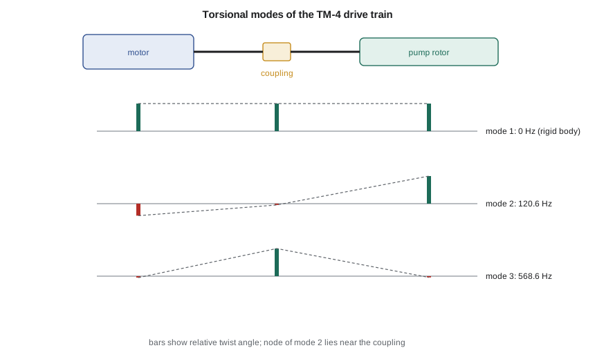
Because the chain is not attached to ground, K is singular, and one natural frequency is zero: the whole train can turn as a rigid body, which is of course what it does when it runs. The rigid-body mode is the reason the first frequency printed by the program is 0.0 Hz with all three mode shape values equal.
Solving the eigenvalue problem numerically
For two degrees of freedom, a determinant and a quadratic suffice. For more, a numerical method is used. A clean approach for symmetric problems is to transform to standard form. With \(\mathbf{x} = \mathbf{M}^{-1/2}\mathbf{q}\), the problem becomes \(\mathbf{A}\mathbf{q} = \omega^2\mathbf{q}\) with \(\mathbf{A} = \mathbf{M}^{-1/2}\mathbf{K}\mathbf{M}^{-1/2}\), a symmetric matrix. For a diagonal mass matrix, M^(−1/2) is just the diagonal of 1/√J_i. The Jacobi method then applies a sequence of plane rotations, each chosen to zero one off-diagonal element, until A is diagonal. The diagonal elements are the eigenvalues ω_i², and the accumulated rotations are the eigenvectors. The method is simple, robust and accurate for small matrices; finite element programs use more efficient methods, such as Lanczos iteration, for thousands of degrees of freedom, but the idea is the same.
# Torsional modes of the TM-4 drive train: motor rotor, coupling hub and pump rotor
import math
J = [0.48, 0.035, 0.21]             # polar inertias, kg m^2: motor, coupling, pump rotor
kt = [3.1e5, 1.15e5]                # shaft stiffnesses, N m/rad: motor shaft, coupling + pump shaft
def torsional_modes(J, kt):
    """Natural frequencies (Hz) and mode shapes of a three-inertia chain by the Jacobi method."""
    n = 3
    K = [
        [kt[0], -kt[0], 0.0],
        [-kt[0], kt[0] + kt[1], -kt[1]],
        [0.0, -kt[1], kt[1]],
    ]
    # Mass-normalize: A = M^-1/2 K M^-1/2 is symmetric, so the Jacobi method applies
    s = [1 / math.sqrt(j) for j in J]
    A = [ [K[i][k] * s[i] * s[k] for k in range(n)] for i in range(n)]
    V = [ [1.0 if i == k else 0.0 for k in range(n)] for i in range(n)]
    for sweep in range(50):
        off = sum(A[i][k]**2 for i in range(n) for k in range(n) if i != k)
        if off < 1e-18: break
        for p in range(n):
            for q in range(p + 1, n):
                if abs(A[p][q]) < 1e-30: continue
                th = 0.5 * math.atan2(2 * A[p][q], A[q][q] - A[p][p])
                c, sn = math.cos(th), math.sin(th)
                for k in range(n):        # rotate columns p, q
                    akp, akq = A[k][p], A[k][q]
                    A[k][p], A[k][q] = c * akp - sn * akq, sn * akp + c * akq
                for k in range(n):        # rotate rows p, q
                    apk, aqk = A[p][k], A[q][k]
                    A[p][k], A[q][k] = c * apk - sn * aqk, sn * apk + c * aqk
                for k in range(n):
                    vkp, vkq = V[k][p], V[k][q]
                    V[k][p], V[k][q] = c * vkp - sn * vkq, sn * vkp + c * vkq
    order = sorted(range(n), key=lambda i: A[i][i])
    modes = []
    for idx in order:
        lam = max(A[idx][idx], 0.0)
        phi = [V[i][idx] * s[i] for i in range(n)]        # back to physical coordinates
        big = max(phi, key=abs); phi = [p / big for p in phi]
        modes.append((math.sqrt(lam) / 2 / math.pi, phi))

    return modes

modes = torsional_modes(J, kt); n = 3
for f, phi in modes:
    print(f"Mode at {f:7.1f} Hz: motor {phi[0]:+.3f}, coupling {phi[1]:+.3f}, pump {phi[2]:+.3f}")
# Orthogonality: phi_i^T M phi_j = 0 for i != j
p1, p2 = modes[1][1], modes[2][1]
print(f"Check phi1' M phi2 = {sum(J[i]*p1[i]*p2[i] for i in range(n)):.2e} (zero within rounding)")
# Excitation check: running speed and vane pass (7 vanes per stage) against mode 2
f_run = 3560 / 60
for name, fe in (("1x running", f_run), ("2x line, 60 Hz grid", 120.0), ("vane pass 7x", 7 * f_run)):
    near = min(modes[1:], key=lambda m: abs(m[0] - fe))[0]
    print(f"{name:20s} {fe:6.1f} Hz: nearest torsional mode {near:6.1f} Hz, separation {abs(near-fe)/fe:5.1%}")
# Fix: a softer elastomeric coupling lowers mode 2 well below 120 Hz
for kc in (1.15e5, 0.60e5, 0.35e5):
    f2 = torsional_modes(J, [kt[0], kc])[1][0]
print(f"coupling + shaft stiffness {kc/1e3:5.0f} kN m/rad: mode 2 at {f2:6.1f} Hz, separation from 120 Hz {abs(f2-120)/120:5.1%}")Mode at 0.0 Hz: motor +1.000, coupling +1.000, pump +1.000 Mode at 120.6 Hz: motor -0.434, coupling -0.048, pump +1.000 Mode at 568.6 Hz: motor -0.053, coupling +1.000, pump -0.045 Check phi1' M phi2 = -3.69e-18 (zero within rounding) 1x running 59.3 Hz: nearest torsional mode 120.6 Hz, separation 103.2% 2x line, 60 Hz grid 120.0 Hz: nearest torsional mode 120.6 Hz, separation 0.5% vane pass 7x 415.3 Hz: nearest torsional mode 568.6 Hz, separation 36.9% coupling + shaft stiffness 115 kN m/rad: mode 2 at 120.6 Hz, separation from 120 Hz 0.5% coupling + shaft stiffness 60 kN m/rad: mode 2 at 93.1 Hz, separation from 120 Hz 22.4% coupling + shaft stiffness 35 kN m/rad: mode 2 at 73.5 Hz, separation from 120 Hz 38.8%
The program finds the rigid-body mode, a second mode at 120.6 Hz and a third at 568.6 Hz. In the second mode the motor and pump rotors twist against each other: normalized to the pump, the motor moves −0.43 and the coupling −0.05, so the node lies close to the coupling, where the twisting is concentrated. In the third mode the light coupling hubs oscillate between the two heavy rotors, which hardly move. The excitation check shows the problem at once. Running speed, 59.3 Hz, and the vane-pass frequency of the seven-vane impellers, 415 Hz, are well separated from both modes, but twice line frequency, 120 Hz, is within half a percent of the second mode.
Where does a 120 Hz torque come from?
An induction motor's electromagnetic torque is not perfectly steady. Any imbalance in the supply voltages, or asymmetry in the motor, produces a torque pulsation at twice line frequency: 120 Hz on the 60 Hz grids of Canada and the United States. Its amplitude is usually small, but a lightly damped torsional mode at 120.6 Hz amplifies it many times. Gear couplings add little damping. The polished and pitted teeth are the signature of an alternating torque large enough to slide the teeth against each other hundreds of times a second. Lucie confirms the diagnosis with a strain-gauge telemetry system on the coupling spacer, which shows an alternating torque at 120 Hz of about 30 percent of the running torque.
Orthogonality and modal coordinates
The mode shapes of a symmetric system have a powerful property: they are orthogonal with respect to both the mass and stiffness matrices,
The program checks the first of these numerically: the product for modes 2 and 3 is of the order of 10⁻¹⁸, zero within rounding. Orthogonality means that the modes can be used as a set of independent coordinates. Writing \(\mathbf{x} = \sum_i \boldsymbol{\phi}_i q_i(t)\) and premultiplying by φ_jᵀ uncouples the equations:
Each mode behaves as an independent single-degree-of-freedom system with its own modal mass, modal stiffness and modal force. All the results of Lessons 2 to 7 apply to each mode separately, and the physical response is the sum of the modal responses. This is modal superposition, the basis of most structural dynamics software. With damping, the equations uncouple exactly if the damping matrix is proportional to M and K (Rayleigh damping), and approximately if damping is light, which is why engineers usually assign a damping ratio to each mode.
The modal force φ_jᵀF tells which forces can excite which modes. A torque applied at the motor excites mode 2 in proportion to the motor's mode shape value, −0.43; the same torque applied at a node would not excite the mode at all. Likewise, a sensor placed at a node would not see it. Mode shapes therefore guide both the search for the cause and the choice of measurement point.
Experimental modal analysis
The modes of real structures are measured by experimental modal analysis. An instrumented hammer or a shaker excites the structure, accelerometers record the response at many points, and an analyzer computes the frequency response function between each input and output. Each resonance peak gives a natural frequency; its width gives the damping (the half-power method of Lesson 4); and the relative heights and signs of the peaks at different points give the mode shape. Tidewater uses impact modal tests on every new baseplate design and on the TM-4 casing, and compares the results with finite element models. Agreement within a few percent validates the model for use in later design changes. For torsional systems, which are hard to excite and measure directly, the calculated model, checked against a measured torque or speed fluctuation, is usually what engineers rely on.
The fix: retune the drive train
Moving the second mode away from 120 Hz can be done by changing an inertia or a stiffness. Adding inertia to the coupling would do little, since mode 2 is dominated by the two rotors. Changing the coupling stiffness is effective, because the twisting in mode 2 is concentrated across it. The last lines of the program show the effect of replacing the gear coupling with an elastomeric coupling. Reducing the combined coupling and pump shaft stiffness from 115 to 60 kN·m/rad moves mode 2 to 93.1 Hz, 22 percent below 120 Hz and 57 percent above running speed. A still softer coupling, 35 kN·m/rad, moves it to 73.5 Hz, but that is only 24 percent above running speed and close to the range in which start-up transients could excite it. Owen recommends the 60 kN·m/rad coupling, whose rubber elements also add damping.
Worked problem
A quick check by the two-inertia approximation
Before running the program, Owen estimates mode 2 by ignoring the light coupling and treating the train as two inertias J₁ = 0.48 and J₃ = 0.21 kg·m² joined by k₁ and k₂ in series.
Show solution
- Series stiffness: \(k = 1/(1/310 + 1/115)\) kN·m/rad = 83.9 kN·m/rad.
- Two rotors twisting against each other: \(\omega^2 = k(J_1 + J_3)/(J_1J_3) = 83{,}900 \times 0.69/0.1008 = 5.74\times10^5\).
- f = √(5.74×10⁵)/2π = 121 Hz.
Answer: The estimate of 121 Hz agrees with the full model's 120.6 Hz, because the coupling hub's inertia is small. Hand estimates like this are the best check on a computer model's input data.
Lateral modes and the limits of lumped models
The same matrix approach handles lateral vibration of a rotor, a pipe system or a baseplate, with the coordinates now being displacements and rotations at chosen nodes. As the number of nodes increases, the lumped model approaches the continuous system of Lesson 10. Lucie's practical guidance is to use at least four to six nodes per half-wavelength of the highest mode of interest, and to check that adding nodes no longer changes the frequencies of interest. The TM-4's lateral rotordynamic model in Lesson 11 uses forty-eight shaft elements for exactly this reason.
Common mistakes
MistakeTreating the rigid-body zero-frequency mode as an error.
InsteadAn unconstrained chain must have a zero frequency; it is the running motion.
MistakeLooking for torsional vibration with lateral sensors.
InsteadMeasure torque with strain gauges or speed fluctuation with an encoder.
MistakeChanging the parameter with little participation in the mode.
InsteadChange the stiffness or inertia where the mode concentrates strain or motion.
MistakeForgetting electrical excitation at twice line frequency.
InsteadInclude 120 Hz (or 100 Hz on 50 Hz grids) in torsional checks.
MistakeAssuming modal superposition holds with heavy, non-proportional damping.
InsteadIt is exact only for proportional damping; for light damping it is a good approximation.
Summary and key terms
- An n-degree-of-freedom system has n natural frequencies and mode shapes from Kφ = ω²Mφ.
- Free chains have a zero-frequency rigid-body mode; the TM-4 drive train has modes at 0, 120.6 and 568.6 Hz.
- The Jacobi method diagonalizes the symmetric matrix M^(−1/2) K M^(−1/2) to give frequencies and modes.
- Modes are orthogonal with respect to M and K, so modal coordinates uncouple the equations of motion.
- The second torsional mode at 120.6 Hz coincides with twice line frequency, explaining the coupling wear.
- A softer elastomeric coupling moves mode 2 to 93.1 Hz, well away from 59.3 and 120 Hz.
- Generalized eigenvalue problem
- Kφ = ω²Mφ for natural frequencies and mode shapes of a multi-degree system.
- Rigid-body mode
- A zero-frequency mode in which an unconstrained system moves without deforming.
- Jacobi method
- An iterative method for symmetric eigenvalue problems using plane rotations.
- Orthogonality
- The property that φ_iᵀMφ_j = 0 and φ_iᵀKφ_j = 0 for different modes.
- Modal coordinates
- Coordinates that measure how much of each mode is present in the motion.
- Modal mass
- φᵀMφ for a mode.
- Modal superposition
- Finding the response as the sum of independent modal responses.
- Proportional damping
- A damping matrix that is a combination of the mass and stiffness matrices.
- Torsional vibration
- Oscillating twist of shafts and rotors about their axis.
- Experimental modal analysis
- Measurement of natural frequencies, damping and mode shapes from frequency response functions.
Practice problems
Work each problem on paper first, then reveal the answer to check.
Two rotors of 1.0 and 0.5 kg·m² are joined by a shaft of 50 kN·m/rad. Find the torsional natural frequency.
Show answer
ω² = 50,000 × 1.5/0.5 = 150,000; f = 61.6 Hz.
Where is the node of that mode?
Show answer
At one third of the shaft length from the heavier rotor, since the angles are in inverse proportion to the inertias.
Why is one natural frequency of an unconstrained chain zero?
Show answer
The whole chain can rotate as a rigid body without twisting any spring.
Two mode shapes are [1, 0.5] and [1, −2] for M = diag(1, 1). Are they orthogonal?
Show answer
Yes: 1 − 1 = 0.
In the program, raise the coupling hub inertia to 0.10 kg·m². What happens to mode 3?
Show answer
It falls substantially, to about 350 Hz, while mode 2 barely changes.
Why does an elastomeric coupling help besides lowering the stiffness?
Show answer
Its rubber elements add damping to the torsional mode.
Lesson quiz · 5 questions
Score 60% or more to complete this lesson.
Create a free account to save your progress, take quizzes and earn a certificate.