
MEC-370 · Lesson 9 of 12 · 27 min
Isentropic flow in nozzles
The 600 mm transmission main between Northside and the elevated reservoir has eleven air valves at its high points. When the main is filled after a repair, air must leave through them as fast as water enters, or the trapped air compresses, slows the filling and can cause pressure surges when it finally escapes. When the main is in service, small amounts of air come out of solution and collect at the high points, reducing the pipe's capacity until the valves release them. And when the main is drained, the valves must let air in to prevent a vacuum that could collapse the pipe or draw in contaminated water. Two of the valves failed last winter, and Hana has asked Jun to check whether the remaining valves have the right orifice sizes. The calculation is a compressible-flow problem: air flowing through a small opening under a pressure difference that can be large enough to make the flow sonic.
Isentropic flow with area change
Lesson 8 showed that for steady one-dimensional isentropic flow, \(dA/A = (M^2 - 1)\,dV/V\). A subsonic flow accelerates in a converging passage, a supersonic flow accelerates in a diverging one, and the sonic condition M = 1 can occur only at a minimum area, a throat. To work with finite changes it is convenient to use the sonic state as a reference. Denote by A* the area at which the flow would be exactly sonic; for a given mass flow and stagnation state, conservation of mass then gives the area-Mach relation:
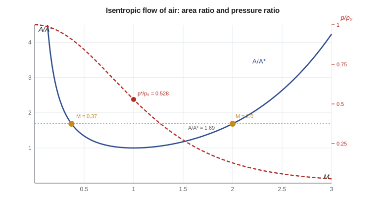
For every area ratio greater than one there are two solutions, one subsonic and one supersonic. The ratio has a minimum of exactly 1 at M = 1. Combined with the stagnation relations of Lesson 8, it gives the pressure, temperature and density anywhere in the passage. The values at the sonic point, called critical values, are fixed fractions of the stagnation values. For air with k = 1.4:
# Isentropic flow: area-Mach relation, choking, and sizing an air-release orifice
import math
k, R = 1.4, 287.0
def A_ratio(M):                      # A/A* for isentropic flow
    return (1 / M) * ((2 / (k + 1)) * (1 + (k - 1) / 2 * M**2)) ** ((k + 1) / (2 * (k - 1)))
def M_from_A(Ar, supersonic):        # invert A/A* by bisection
    lo, hi = (1.0, 10.0) if supersonic else (1e-6, 1.0)
    for _ in range(200):
        mid = (lo + hi) / 2
        if (A_ratio(mid) > Ar) == supersonic: hi = mid
        else: lo = mid
    return (lo + hi) / 2
pr = lambda M: (1 + (k - 1) / 2 * M**2) ** (-k / (k - 1))   # p/p0
Tr = lambda M: 1 / (1 + (k - 1) / 2 * M**2)                 # T/T0
crit = pr(1.0)
print(f"Critical pressure ratio p*/p0 = {crit:.4f}; T*/T0 = {Tr(1.0):.4f}")
print(" M     A/A*    p/p0    T/T0")
for M in (0.2, 0.5, 0.8, 1.0, 1.5, 2.0, 2.5, 3.0):
    print(f" {M:3.1f}  {A_ratio(M):6.3f}  {pr(M):6.4f}  {Tr(M):6.4f}")

# Laboratory blowdown nozzle: exit area 1.6875 times the throat
Ae_At = 1.6875
for sup in (False, True):
    Me = M_from_A(Ae_At, sup)
    print(f"Exit Mach {'supersonic' if sup else 'subsonic'} branch: {Me:.3f}, p_e/p0 = {pr(Me):.4f}")

# Choked mass flow through an orifice: mdot = Cd A p0 sqrt(k/(R T0)) (2/(k+1))^((k+1)/(2(k-1)))
def mdot_orifice(d, p0, T0, pb, Cd=0.62):
    A = math.pi * d**2 / 4
    if pb / p0 <= crit:              # choked: independent of back pressure
        return Cd * A * p0 * math.sqrt(k / (R * T0)) * (2 / (k + 1)) ** ((k + 1) / (2 * (k - 1))), True
    M = math.sqrt(2 / (k - 1) * ((p0 / pb) ** ((k - 1) / k) - 1))
    T = T0 * Tr(M); rho = pb / (R * T)
    return Cd * A * rho * M * math.sqrt(k * R * T), False
patm = 97.4e3; T0 = 283.15
# Air-release valve on the 600 mm main: small orifice venting accumulated air under pressure
for pg in (50e3, 300e3, 600e3):
    m, ch = mdot_orifice(0.005, patm + pg, T0, patm)
    rho_n = patm / (R * T0)
    print(f"5 mm orifice at {pg/1000:.0f} kPa gauge: {m*1000:.2f} g/s ({m/rho_n*1000:.1f} L/s of free air), {'choked' if ch else 'not choked'}")
# Large orifice during pipe filling: air must leave as fast as water enters
Vfill, Dmain = 0.30, 0.600
Qair = Vfill * math.pi * Dmain**2 / 4
for d in (0.025, 0.050, 0.075):
    # find the internal pressure needed to vent Qair (free air) through orifice d
    lo, hi = patm * 1.0001, patm * 3
    for _ in range(100):
        mid = (lo + hi) / 2
        m, ch = mdot_orifice(d, mid, T0, patm)
        if m / (patm / (R * T0)) > Qair: hi = mid
        else: lo = mid
print(f"Filling at {Vfill} m/s ({Qair*1000:.0f} L/s of air): {d*1000:.0f} mm orifice needs {(mid-patm)/1000:6.1f} kPa above atmosphere{' (choked)' if ch else ''}")Critical pressure ratio p*/p0 = 0.5283; T*/T0 = 0.8333 M A/A* p/p0 T/T0 0.2 2.964 0.9725 0.9921 0.5 1.340 0.8430 0.9524 0.8 1.038 0.6560 0.8865 1.0 1.000 0.5283 0.8333 1.5 1.176 0.2724 0.6897 2.0 1.688 0.1278 0.5556 2.5 2.637 0.0585 0.4444 3.0 4.235 0.0272 0.3571 Exit Mach subsonic branch: 0.372, p_e/p0 = 0.9088 Exit Mach supersonic branch: 2.000, p_e/p0 = 0.1278 5 mm orifice at 50 kPa gauge: 4.14 g/s (3.5 L/s of free air), not choked 5 mm orifice at 300 kPa gauge: 11.62 g/s (9.7 L/s of free air), choked 5 mm orifice at 600 kPa gauge: 20.39 g/s (17.0 L/s of free air), choked Filling at 0.3 m/s (85 L/s of air): 25 mm orifice needs 48.2 kPa above atmosphere Filling at 0.3 m/s (85 L/s of air): 50 mm orifice needs 2.9 kPa above atmosphere Filling at 0.3 m/s (85 L/s of air): 75 mm orifice needs 0.6 kPa above atmosphere
The table that the program prints is a short version of the isentropic flow tables printed in every gas dynamics text. They make hand calculations quick: given a Mach number, read off A/A*, p/p₀ and T/T₀; given an area ratio or a pressure ratio, find the Mach number. For computer work, the relations are simply solved numerically, as the program does by bisection.
Choking and the maximum mass flow
The mass flow through a passage is \(\dot{m} = \rho A V\). Writing ρ and V in terms of the stagnation state and the Mach number, and evaluating at a throat where M = 1, gives the maximum possible mass flow through that throat for a given stagnation pressure and temperature:
Once the throat is sonic, the flow is said to be choked. Lowering the downstream pressure further cannot increase the mass flow, because the sonic throat is the place where information travels upstream at exactly the flow speed: news of the lower downstream pressure cannot reach the reservoir. The mass flow then depends only on the upstream stagnation pressure and temperature and on the throat area. This is a very useful property. Choked orifices, called critical flow nozzles or sonic nozzles, are used as flow standards because they deliver a mass flow that is independent of conditions downstream.
For air discharging into the atmosphere through a simple orifice, the flow chokes when the absolute upstream pressure exceeds about 1.89 times the absolute downstream pressure, the reciprocal of 0.528. At Omaha's atmospheric pressure of about 97.4 kPa, that is an internal gauge pressure above about 87 kPa. The transmission main runs at several hundred kilopascals, so air released from it under pressure always leaves at sonic speed in the orifice's vena contracta.
The converging nozzle and back pressure
Consider a converging nozzle fed from a large reservoir at stagnation pressure p₀ and discharging into a space at back pressure p_b. With p_b equal to p₀, there is no flow. As p_b is lowered, flow starts and increases, and the exit pressure equals the back pressure. When p_b reaches the critical value 0.528 p₀, the exit becomes sonic and the mass flow reaches its maximum. Lowering p_b further changes nothing inside the nozzle: the exit stays sonic at 0.528 p₀, and the gas expands outside the nozzle in a pattern of expansion waves and shocks, the diamonds visible in the exhaust of a jet engine or a compressed-air blowgun. A converging nozzle can never deliver a supersonic jet at its exit.
The converging-diverging nozzle
To produce supersonic flow, the passage must continue to widen after the sonic throat. Carl Gustaf de Laval developed this shape for steam turbines in the 1880s, and it is used today in rocket engines, steam turbines, supersonic wind tunnels and some ejectors. A converging-diverging nozzle has a design back pressure at which the flow accelerates smoothly through Mach 1 at the throat and leaves the exit at the design Mach number, with the exit pressure equal to the back pressure. The exit Mach number depends only on the exit-to-throat area ratio.
The program examines the blowdown nozzle in the university gas dynamics laboratory where Jun took his compressible flow course. It has an exit area 1.6875 times its throat area. Two isentropic solutions fit that area ratio: a subsonic exit at Mach 0.37 with p_e/p₀ = 0.909, where the flow speeds up to just below sonic in the throat and slows again, and a supersonic exit at Mach 2.0 with p_e/p₀ = 0.128. At back pressures between these values, neither isentropic solution can match the back pressure, and a shock wave forms in the diverging section or outside the exit. Lesson 10 locates it.
Worked problem
Designing a Mach 2 nozzle
Air at 600 kPa and 300 K supplies a nozzle that must deliver 0.50 kg/s at Mach 2.0. Find the throat and exit areas and the exit pressure and temperature.
Show solution
- \[A^* = \frac{\dot m \sqrt{T_0}}{0.0404\,p_0} = \frac{0.50\sqrt{300}}{0.0404 \times 600\,000} = 3.57\times10^{-4}\ \text{m}^2\]
- That is a throat about 21 mm in diameter. At M = 2.0, \(A/A^* = 1.6875\), so \(A_e = 6.03 \times 10^{-4}\) m², about 28 mm in diameter.
- \(p_e = 0.1278 \times 600 = 76.7\) kPa; \(T_e = 0.5556 \times 300 = 167\) K, or −106 °C.
Answer: The exit air is very cold, because its enthalpy has been converted into kinetic energy at about 518 m/s. At back pressures near 77 kPa the nozzle runs at its design condition. Discharged into a room at about 95 to 100 kPa, it would be overexpanded and a shock system would form at the exit.
Flow through air valves
Air valves for water mains come in three kinds. An air-release valve has a small orifice, typically a few millimeters across, controlled by a float; it releases the small pockets of air that collect in a pressurized main. An air and vacuum valve has a large orifice, comparable to a fraction of the pipe diameter, that lets large volumes of air out during filling and in during draining, but closes when water arrives and cannot open again while the main is pressurized. A combination valve has both. AWWA C512 covers these valves, and AWWA Manual M51 describes how to locate and size them.
The program examines both duties for one high point. With a 5 mm release orifice and a discharge coefficient of 0.62, the flow at 50 kPa gauge is not choked, because the pressure ratio is less than 1.89, and the valve releases about 4 g/s of air. At 300 and 600 kPa it is choked and releases about 12 and 20 g/s, or roughly 10 and 17 liters of free air per second. Because the choked mass flow is proportional to the absolute upstream pressure, the valve releases air faster at higher line pressure, which is helpful.
For filling, the main is filled at a controlled velocity of 0.30 m/s, a common practice limit for large mains, which displaces 85 L/s of air. The program finds the internal pressure needed to push that much air out through orifices of three sizes. A 25 mm orifice would need about 48 kPa above atmospheric pressure, and the air pocket would cushion and then slam as water reached the valve. A 50 mm orifice needs only about 3 kPa, and a 75 mm orifice about 0.6 kPa. Many design guides limit the pressure differential across an air and vacuum orifice during filling to a few kilopascals, roughly 2 psi or about 14 kPa at most, to avoid slam and premature closure; the 50 mm orifice meets that comfortably.
Worked problem
Choked release at line pressure
An air-release valve with a 5 mm orifice (C_d = 0.62) sees air at 600 kPa gauge and 10 °C in the main, discharging to the atmosphere at 97.4 kPa. Find the mass flow.
Show solution
- Absolute upstream pressure \(p_0 = 600 + 97.4 = 697.4\) kPa; the ratio to atmosphere exceeds 1.89, so the flow is choked.
- Orifice area \(A = \pi(0.005)^2/4 = 1.963\times10^{-5}\) m².
- \(\dot m = 0.62 \times 0.0404 \times 1.963\times10^{-5} \times 697\,400/\sqrt{283.15} = 0.0204\) kg/s.
Answer: About 20 g/s. A pocket of 50 L of air compressed in the main at 600 kPa gauge contains about 0.4 kg, so the valve clears it in about 20 seconds.
Other applications of choked flow
Choked flow appears wherever gas leaves a high-pressure system. Safety relief valves on compressed-air receivers and steam boilers are sized with choked-flow equations, because at their set pressure the flow through them is sonic; the receiver's relief valve must pass the compressor's full output without the pressure rising more than a set percentage above the set point. Leaks in compressed-air systems are almost always choked, so a leak's flow is proportional to the absolute pressure and the leak area, and plant energy audits estimate leak losses that way: a single 3 mm leak at 700 kPa gauge wastes several liters of free air per second, which adds up to thousands of kilowatt-hours a year. Gas-turbine and jet-engine nozzles, rocket nozzles, steam-turbine blade passages and the throats of supersonic wind tunnels are all designed with the relations in this lesson.
Worked problem
Cost of a compressed-air leak
A 3 mm leak (C_d = 0.65) in the plant's 700 kPa gauge instrument air system, at 20 °C, runs all year. The compressor uses about 0.12 kWh of electricity per cubic meter of free air. Estimate the annual energy waste at 97.4 kPa atmospheric pressure.
Show solution
- The flow is choked. With \(A = 7.07\times10^{-6}\) m² and \(p_0 \approx 795\) kPa, \(\dot m = 0.65 \times 0.0404 \times 7.07\times10^{-6} \times 795\,000/\sqrt{293.15} = 8.6\) g/s.
- Free air at about 1.14 kg/m³: about 7.6 L/s, or 240,000 m³ a year.
- Energy: \(240\,000 \times 0.12 \approx 29\) MWh a year.
Answer: One small leak costs roughly 29 MWh a year, which is why compressed-air leak surveys are among the first energy-saving measures in any plant.
In the United States, safety relief valves on air receivers are certified under the ASME Boiler and Pressure Vessel Code, with their capacity stamped on the valve, and state inspectors check them. Air valves on Platte Bluffs Water's mains are specified to AWWA C512 and located following AWWA Manual M51.
Common mistakes
MistakeExpecting more flow through a choked orifice by lowering the back pressure.
InsteadOnce sonic, the mass flow depends only on upstream stagnation conditions and the throat area.
MistakeUsing gauge pressure in the choked-flow formula.
InsteadUse absolute stagnation pressure and absolute temperature.
MistakeAssuming a converging nozzle gives a supersonic jet at high supply pressure.
InsteadThe exit of a converging nozzle stays sonic; supersonic flow needs a diverging section.
MistakeChoosing the subsonic area-Mach solution for a supersonic nozzle.
InsteadEach area ratio has two solutions; the design condition selects one.
MistakeSizing an air and vacuum orifice from the main's operating pressure.
InsteadSize it for filling and draining rates with a small allowed differential pressure.
Summary and key terms
- The area-Mach relation A/A* gives a subsonic and a supersonic Mach number for each area ratio, with A/A* = 1 at M = 1.
- Critical ratios for air are p*/p₀ = 0.528 and T*/T₀ = 0.833.
- A choked throat passes the maximum mass flow ṁ = 0.0404 A*p₀/√T₀ for air, independent of the back pressure.
- Converging nozzles reach at most sonic exit speed; converging-diverging nozzles produce supersonic flow at their design back pressure.
- A 5 mm air-release orifice on the main is choked above about 1.89 times atmospheric pressure and releases about 20 g/s at 600 kPa gauge.
- Air and vacuum orifices are sized for filling and draining with only a few kilopascals of differential; 50 mm suffices here.
- Area-Mach relation
- The relation between local area and Mach number in isentropic flow, A/A*.
- Throat
- The minimum-area section of a nozzle.
- Critical pressure ratio
- The ratio p*/p₀ at which flow becomes sonic, 0.528 for air.
- Choked flow
- Flow in which a throat is sonic, so the mass flow cannot increase as back pressure falls.
- Back pressure
- The pressure in the space into which a nozzle discharges.
- Converging-diverging nozzle
- A nozzle with a throat followed by a widening section, able to produce supersonic flow.
- Design condition
- The back pressure at which a nozzle expands isentropically to its exit Mach number.
- Air-release valve
- A float valve with a small orifice that releases air from a pressurized main.
- Air and vacuum valve
- A valve with a large orifice that vents air during filling and admits it during draining.
- Critical flow nozzle
- A choked nozzle used as a mass flow standard.
Practice problems
Work each problem on paper first, then reveal the answer to check.
Air in a tank at 400 kPa and 300 K discharges through a 10 mm throat. Find the choked mass flow (C_d = 1).
Show answer
0.0404 × 7.854 × 10⁻⁵ × 400,000/17.32 ≈ 0.073 kg/s.
Find the exit Mach number of a converging-diverging nozzle with A_e/A* = 2.637 on its supersonic branch.
Show answer
2.5.
For the nozzle in the previous problem, what back pressure ratio gives the design condition?
Show answer
p_b/p₀ = 0.0585.
What is the speed of the air at the exit of the Mach 2 nozzle example?
Show answer
M × √(kRT) = 2 × √(1.4 × 287 × 167) ≈ 518 m/s.
In the program, change the filling velocity to 0.6 m/s. What happens to the pressure needed with the 50 mm orifice?
Show answer
It rises to about 11 kPa, approaching the usual limit.
Why does a choked leak waste more free air at higher line pressure?
Show answer
Choked mass flow is proportional to absolute upstream pressure.
Lesson quiz · 5 questions
Score 60% or more to complete this lesson.
Create a free account to save your progress, take quizzes and earn a certificate.