
MEC-370 · Lesson 6 of 12 · 27 min
Drag on bluff and streamlined bodies
Three of Jun's tasks this term turn on drag. The grit chamber at the head of the treatment plant must let sand settle while lighter organic matter stays in suspension, and its design depends on how fast grains fall through water. The new intake screen must withstand the river's push during spring floods. And the elevated water reservoir at Northside, a 16 m spherical tank on a 30 m column, is due for a structural review that includes a check of wind loads and of vortex-induced vibration of its column. All three need the same idea: the force a fluid exerts on a body moving relative to it, and how that force depends on the body's shape and the Reynolds number.
Drag and its two parts
The total force a fluid exerts on a body is the integral of pressure and shear stress over its surface. The component along the flow is drag; the component across it is lift, the subject of Lesson 7. Drag is written with a drag coefficient based on a reference area A, usually the frontal area for bluff bodies and the plan or wetted area for plates and wings:
Drag has two parts. Friction drag comes from wall shear and dominates for streamlined bodies and plates aligned with the flow, as in Lessons 4 and 5. Pressure drag, also called form drag, comes from the difference between high pressure on the front and low pressure in the separated wake behind. It dominates for bluff bodies, whose shapes force the boundary layer to separate. A flat plate across the flow has almost no friction drag, because the shear acts perpendicular to the flow direction, and almost all pressure drag. The same plate aligned with the flow has only friction drag, about a hundred times smaller.
Drag coefficients and Reynolds number
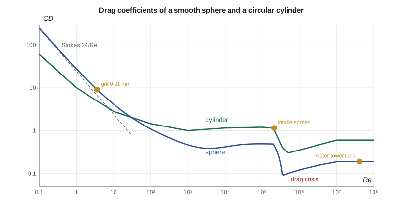
Dimensional analysis in Lesson 2 showed that the drag coefficient of a body of fixed shape depends on the Reynolds number and, for rough bodies, the relative roughness. At very low Reynolds number, the flow creeps around the body without separating and inertia is negligible. Stokes solved this case for a sphere in 1851:
As Re rises, the boundary layer separates and a wake forms; the drag coefficient falls more slowly and levels off at roughly 0.4 to 0.5 for a sphere between Re ≈ 10³ and 2 × 10⁵. Then something dramatic happens. Near Re ≈ 3 × 10⁵ for a smooth sphere, the boundary layer becomes turbulent before it separates, separation moves back from about 80° to about 120°, the wake narrows and the drag coefficient falls abruptly to about 0.1 to 0.2. This is the drag crisis. Circular cylinders show the same behavior, with C_D falling from about 1.2 to about 0.3 near Re ≈ 3 × 10⁵ and recovering partly at higher Re. Roughness moves the crisis to a lower Reynolds number, which is what the dimples on a golf ball accomplish.
| Body | Reference area | Typical \(C_D\) | Notes |
|---|---|---|---|
| Flat plate across the flow | Frontal | 1.2 to 2.0 | Rises with aspect ratio; 2.0 for a very long plate |
| Circular cylinder, subcritical | Frontal (D × L) | 1.0 to 1.2 | Re from 10⁴ to 2 × 10⁵ |
| Circular cylinder, supercritical | Frontal | 0.3 to 0.7 | Depends on roughness and Re |
| Sphere, subcritical | Frontal | 0.4 to 0.5 | Re from 10³ to 2 × 10⁵ |
| Sphere, supercritical | Frontal | 0.1 to 0.2 | Above the drag crisis |
| Streamlined body of revolution | Frontal | 0.04 to 0.1 | Little separation |
| Square section, flat face to flow | Frontal | about 2.0 | Sharp edges fix separation; little Re effect |
| Person standing | Frontal | 1.0 to 1.3 | About 0.6 to 0.8 m² of frontal area |
Sharp-edged bodies, such as plates and square sections, separate at their edges whatever the Reynolds number, so their drag coefficients hardly change once Re is above about 10³. Rounded bodies are sensitive, because the separation point moves. This distinction is why building codes give fixed force coefficients for most structural shapes but treat round chimneys, tanks and towers with care.
Settling grit: drag at low Reynolds number
A grain falling steadily through still water reaches its terminal velocity when its weight, less buoyancy, equals its drag:
Because C_D depends on the Reynolds number, which depends on V_t, the equation is solved by iteration. The program starts from Stokes' law and repeats using a standard curve fit for the sphere drag coefficient until the speed converges. Grit chambers are commonly designed to remove sand grains of about 0.2 mm and larger with a specific gravity near 2.65.
# Drag on bluff bodies: grit settling, an intake screen, and wind on the elevated water tower
import math
g = 9.81
def cd_sphere(Re):                 # standard drag curve fit, valid to about Re = 2e5
    return 24 / Re * (1 + 0.15 * Re**0.687) + 0.42 / (1 + 4.25e4 * Re**-1.16)
# 1. Terminal settling speed of sand grains in the grit chamber (water at 10 C)
rho_w, mu_w, rho_s = 999.7, 1.31e-3, 2650.0
for d in (0.10e-3, 0.21e-3, 0.50e-3, 1.0e-3):
    v = (rho_s - rho_w) * g * d**2 / (18 * mu_w)          # start from Stokes' law
    for _ in range(100):
        Re = rho_w * v * d / mu_w
        v = math.sqrt(4 * (rho_s - rho_w) * g * d / (3 * cd_sphere(Re) * rho_w))
    Re = rho_w * v * d / mu_w
    print(f"d = {d*1000:.2f} mm: settling speed {v*1000:5.1f} mm/s, Re = {Re:5.1f}, Stokes would give {(rho_s-rho_w)*g*d**2/(18*mu_w)*1000:6.1f} mm/s")

# 2. Cylindrical wedge-wire intake screen in the river current
D, Ls, V = 0.9, 2.4, 0.30
Re = rho_w * V * D / mu_w
Cd = 1.2                           # subcritical circular cylinder
print(f"\nScreen: Re = {Re:.1e}, drag {Cd*0.5*rho_w*V**2*D*Ls:.0f} N; during ice-free flood at 1.5 m/s {Cd*0.5*rho_w*1.5**2*D*Ls:.0f} N")

# 3. Wind on the elevated water tower: air density from local station pressure
p, T = 97.4e3, 273.15 - 10.0     # station pressure and a cold, windy day
rho_a = p / (287.0 * T)
mu_a = 1.68e-5
V = 35.0                           # design gust speed used for this check, m/s
D_tank, D_col, H_col = 16.0, 3.0, 30.0
Re_t = rho_a * V * D_tank / mu_a
F_tank = 0.2 * 0.5 * rho_a * V**2 * math.pi * D_tank**2 / 4   # supercritical sphere, C_D about 0.2
F_tank_sub = 0.47 * 0.5 * rho_a * V**2 * math.pi * D_tank**2 / 4
F_col = 0.7 * 0.5 * rho_a * V**2 * D_col * H_col                # supercritical cylinder, C_D about 0.7
print(f"\nAir density {rho_a:.3f} kg/m3; tank Reynolds number {Re_t:.1e}")
print(f"Tank drag {F_tank/1000:.0f} kN (C_D 0.2); it would be {F_tank_sub/1000:.0f} kN at the subcritical C_D 0.47")
print(f"Column drag {F_col/1000:.0f} kN; overturning moment at the base {(F_tank*(H_col+D_tank/2) + F_col*H_col/2)/1000:,.0f} kN.m")
# 4. Vortex shedding from the column: wind speed that matches its natural frequency
St, fn = 0.20, 1.1                 # Strouhal number and the column's first natural frequency, Hz
V_cr = fn * D_col / St
print(f"Shedding frequency at 35 m/s {St*V/D_col:.2f} Hz; lock-in wind speed for f_n = {fn} Hz is {V_cr:.1f} m/s")d = 0.10 mm: settling speed 6.3 mm/s, Re = 0.5, Stokes would give 6.9 mm/s d = 0.21 mm: settling speed 22.3 mm/s, Re = 3.6, Stokes would give 30.3 mm/s d = 0.50 mm: settling speed 70.4 mm/s, Re = 26.9, Stokes would give 171.6 mm/s d = 1.00 mm: settling speed 143.4 mm/s, Re = 109.5, Stokes would give 686.6 mm/s Screen: Re = 2.1e+05, drag 117 N; during ice-free flood at 1.5 m/s 2915 N Air density 1.290 kg/m3; tank Reynolds number 4.3e+07 Tank drag 32 kN (C_D 0.2); it would be 75 kN at the subcritical C_D 0.47 Column drag 50 kN; overturning moment at the base 1,954 kN.m Shedding frequency at 35 m/s 2.33 Hz; lock-in wind speed for f_n = 1.1 Hz is 16.5 m/s
The 0.21 mm design grain settles at about 22 mm/s in 10 °C water. Stokes' law alone would overestimate that by more than a third, because the grain's Reynolds number of 3.6 is already beyond the creeping-flow range. For a 1 mm grain the Stokes estimate is almost five times too high. The chamber's length is set by the time a grain needs to fall through the water depth while the horizontal flow carries it along, so an error in settling speed translates directly into a chamber that is too short. Cold water makes the problem worse: viscosity at 2 °C is about 30 percent higher than at 10 °C, and grains settle more slowly in winter.
Worked problem
Grit chamber length
A horizontal-flow grit chamber is 1.2 m deep, and the horizontal velocity is held at 0.30 m/s. How long must it be for the 0.21 mm grain to reach the floor, with a 50 percent allowance for turbulence and inlet effects?
Show solution
- Settling time from the surface: \(t = 1.2/0.0223 = 54\) s.
- Distance traveled in that time: \(0.30 \times 54 = 16.1\) m.
- With the 50 percent allowance: about 24 m.
Answer: The chamber needs to be about 24 m long. A designer using Stokes' law would have found about 18 m with the allowance, and the chamber would pass too much sand to the plant's pumps and basins.
The intake screen in the river
The intake screen of Lesson 3 is a cylinder 0.9 m in diameter and 2.4 m long. In the normal 0.30 m/s current its Reynolds number is about 2 × 10⁵, just below the drag crisis, so a subcritical drag coefficient of about 1.2 applies and the drag is only about 120 N. In a spring flood at 1.5 m/s the drag rises with the square of the speed to about 2.9 kN, before allowing for debris. Hana asks Jun to design the screen's support for a much larger load, because debris mats and ice can block the screen, turning it into something closer to a solid flat plate with a larger frontal area and a drag coefficient near 2. The fluid mechanics sets the clean-screen load; engineering judgment sets the design load.
Wind on the elevated reservoir
The Northside elevated reservoir has a spherical tank 16 m in diameter on a cylindrical column 3 m in diameter and 30 m high. The structural engineer will use the building code's wind provisions for the final check, but Hana wants an independent estimate from first principles. On a cold, windy day the air is denser than the standard value, and the program finds the density from Omaha's station pressure. At a 35 m/s gust the tank's Reynolds number is about 4 × 10⁷, far above the drag crisis, so the supercritical coefficient of about 0.2 applies to a smooth tank.
The program estimates a tank drag of 32 kN with C_D = 0.2, but 75 kN if the flow behaved as subcritical. The difference shows why the drag crisis matters in design: a model test at too low a Reynolds number would overstate the load by a factor of more than two unless the model were roughened to trip its boundary layer. The column's drag adds about 50 kN, and together they produce an overturning moment at the base of about 1,950 kN·m. The structural engineer will compare this with the code's value, which includes gust effects, the variation of wind speed with height and importance factors.
In the United States, wind loads are calculated from ASCE 7, which gives basic wind speeds on maps by risk category and force coefficients for common shapes, and which most state building codes adopt through the International Building Code. Elevated water tanks are also commonly designed to AWWA D100 for welded steel tanks, which has its own wind provisions.
Vortex shedding
Behind a bluff body, separation does not produce a steady wake. Over a wide range of Reynolds numbers, vortices are shed alternately from each side, forming a regular pattern called a Kármán vortex street. Each vortex shed produces a side force on the body, so the body feels an alternating cross-flow force at the shedding frequency f, which is given by the Strouhal number:
If the shedding frequency approaches a natural frequency of the structure, the vortices and the structure's motion can lock together, and the vibration grows much larger than the force alone would suggest. This is vortex-induced vibration. It sings in power lines, it shook the first tall steel chimneys, and it is a design check for slender columns, risers and pipelines in currents. The reservoir column's first natural frequency is about 1.1 Hz, and the program finds that shedding at that frequency occurs at a wind speed of about 16.5 m/s, a common wind. The structure's damping and mass make the response small for this heavy column, but the check is required, and slender steel stacks are often fitted with helical strakes that break up the coherent shedding.
Streamlining
Streamlining reduces drag by shaping the body so that its boundary layer stays attached as the pressure recovers toward the rear. A well-streamlined strut, with a rounded nose and a long tapering tail, can have a drag coefficient based on frontal area of about 0.06, compared with 1.2 for a circular cylinder of the same thickness: twenty times less. Its friction drag is higher, because it has more surface, but its pressure drag nearly vanishes. The trade-off is length, cost and sensitivity to flow direction: a streamlined strut works only when the flow approaches along its axis. River piers are often given rounded or pointed noses for this reason, and the bars of the intake's trash rack are shaped like flattened teardrops to lower their head loss.
Worked problem
Streamlined trash-rack bars
The intake's trash rack has 120 vertical bars, each 12 mm thick and 3 m long, in a 0.30 m/s approach flow. Compare the drag of round bars (C_D = 1.2) with streamlined bars (C_D = 0.15, based on thickness).
Show solution
- Frontal area of the bars \(= 120 \times 0.012 \times 3 = 4.32\) m².
- Round bars: \(F = 1.2 \times 0.5 \times 998 \times 0.30^2 \times 4.32 = 233\) N.
- Streamlined bars: \(F = 0.15 \times 0.5 \times 998 \times 0.09 \times 4.32 = 29\) N.
Answer: The streamlined bars cut the drag, and the head loss that goes with it, by a factor of eight. When debris collects, the difference disappears, which is why the rack is raked regularly.
Drag of vehicles and people
Drag coefficients for vehicles range from about 0.25 for a modern car to 0.6 or more for a pickup truck or a van, and 0.6 to 0.9 for heavy trucks without fairings. The crew's service truck, with a frontal area of about 3 m² and C_D ≈ 0.55, needs about 21 kW at the wheels just to overcome air drag at 100 km/h, roughly half its total road load. For workers on the reservoir's catwalk, a standing person has a drag area C_D A of about 0.8 m², so a 25 m/s gust pushes with about 300 N, enough to make a fall-protection harness more than a formality.
Common mistakes
MistakeUsing Stokes' law for grit grains above Re ≈ 1.
InsteadIterate with the full drag curve once the Reynolds number exceeds about 1.
MistakeApplying a subcritical C_D to a large round tank in strong wind.
InsteadCheck the Reynolds number; above about 3 × 10⁵ the drag crisis lowers C_D.
MistakeUsing wetted area with bluff-body drag coefficients.
InsteadBluff-body C_D values are based on frontal area unless stated otherwise.
MistakeIgnoring vortex shedding because the mean force is small.
InsteadCheck the lock-in wind speed against natural frequencies; resonance can be large.
MistakeDesigning a screen support for clean-screen drag only.
InsteadAllow for blockage by debris and ice, which can make the screen act as a solid plate.
Summary and key terms
- Drag F_D = C_D ½ρV²A combines friction drag and pressure drag; bluff bodies are dominated by pressure drag from separation.
- At Re below 1, Stokes' law gives C_D = 24/Re for a sphere; at higher Re, C_D levels off near 0.4 to 0.5.
- The drag crisis near Re ≈ 3 × 10⁵ cuts the drag of smooth spheres and cylinders sharply as the layer turns turbulent.
- The 0.21 mm design grit grain settles at about 22 mm/s; Stokes' law would overestimate it by over a third.
- Wind drag on the reservoir tank is about 32 kN at 35 m/s with a supercritical C_D of 0.2.
- Vortex shedding at St ≈ 0.2 produces alternating forces; lock-in with the column's 1.1 Hz frequency occurs near 16.5 m/s.
- Streamlining keeps the boundary layer attached and can cut drag by an order of magnitude.
- Drag
- The component of fluid force on a body parallel to the approaching flow.
- Drag coefficient
- Drag divided by dynamic pressure and a reference area.
- Friction drag
- Drag from wall shear stress.
- Pressure drag
- Drag from the pressure difference between the front of a body and its wake.
- Bluff body
- A body whose shape causes the boundary layer to separate, leaving a wide wake.
- Stokes' law
- The creeping-flow drag on a sphere, F = 3πμVD.
- Terminal velocity
- The steady speed at which drag balances net weight.
- Drag crisis
- The sudden drop in drag of a rounded body when its boundary layer becomes turbulent before separating.
- Strouhal number
- The dimensionless shedding frequency fD/V.
- Vortex-induced vibration
- Oscillation of a structure driven by vortex shedding near its natural frequency.
Practice problems
Work each problem on paper first, then reveal the answer to check.
A 0.1 mm silt grain (specific gravity 2.65) settles in 20 °C water (μ = 1.0 × 10⁻³ Pa·s). Use Stokes' law and check Re.
Show answer
V ≈ 9.0 mm/s; Re ≈ 0.9, so Stokes is about right.
Find the drag on a flat sign of 1 m² (C_D = 1.2) in a 30 m/s wind (ρ = 1.2 kg/m³).
Show answer
648 N.
A 50 mm cable in a 10 m/s wind has St = 0.2. Find the shedding frequency.
Show answer
40 Hz.
In the program, change the grit chamber water to 2 °C (μ = 1.67 × 10⁻³ Pa·s). What is the settling speed of the 0.21 mm grain?
Show answer
About 19 mm/s.
Why does a golf ball with dimples travel farther than a smooth one?
Show answer
Dimples trigger an early turbulent layer, delaying separation and lowering drag at driving speeds.
What drag coefficient would you use for the intake screen if it were fully blocked by debris, and what load at 1.5 m/s?
Show answer
About 2.0 on the frontal area; about 4.8 kN.
Lesson quiz · 5 questions
Score 60% or more to complete this lesson.
Create a free account to save your progress, take quizzes and earn a certificate.