
MEC-370 · Lesson 7 of 12 · 26 min
Lift, airfoils and finite wings
The treatment plant uses about 4 GWh of electricity a year, and the utility's board has asked staff to evaluate a single wind turbine on the plant's land. A developer has proposed a 250 kW machine with a 30 m rotor, and Hana has asked Jun to understand the aerodynamics well enough to review the developer's energy estimate. A modern wind turbine blade is a long, twisted wing, and each section of it works like an airfoil, producing a lift force much larger than its drag. This lesson explains how airfoils produce lift, how lift and drag coefficients behave with angle of attack, why finite wings and blades lose some lift at their tips, and how those ideas apply to a rotating blade. Lesson 12 completes the turbine with the Betz limit and the annual energy.
Lift and the airfoil
Lift is the component of the fluid force perpendicular to the approaching flow. It is written with a lift coefficient based on the planform area S of a wing, or on chord length c per unit span for a two-dimensional section:
An airfoil is a streamlined section with a rounded leading edge and a sharp trailing edge. It is described by its chord c, the straight line from leading to trailing edge; its thickness, usually 6 to 25 percent of the chord; and its camber, the curvature of the mean line halfway between upper and lower surfaces. The angle of attack α is the angle between the chord and the approaching flow. Families of airfoils were cataloged by the US National Advisory Committee for Aeronautics in the 1930s, and the NACA four-digit sections, such as the symmetric 0012 and the cambered 2412, are still used in teaching and in many applications. Wind turbine makers use thicker sections designed for the purpose, especially near the blade root, where strength matters more than aerodynamics.
How lift is produced
There are two correct and consistent explanations of lift, and one popular incorrect one. The first correct explanation is pressure: the flow over the upper surface of a lifting airfoil is faster than the flow under it, so by Bernoulli's equation the pressure on top is lower, and the integrated pressure difference is the lift. The second is momentum: the airfoil turns the flow downward behind it, and by Newton's third law the air pushes the airfoil up. These are two views of the same flow. The incorrect explanation says that air going over the top must take the same time as air going under and therefore travels faster; in fact, particles going over the top arrive at the trailing edge well before their neighbors that went underneath, and the equal-transit-time idea predicts far too little lift.
Lesson 3 showed that a body with circulation Γ in a stream experiences lift \(L' = \rho V \Gamma\), the Kutta-Joukowski theorem. What sets the circulation of an airfoil is its sharp trailing edge. In potential flow without circulation, the rear stagnation point would sit on the upper surface and the flow would have to whip around the sharp edge at infinite speed. Viscosity will not allow that: a starting vortex is shed as the airfoil begins to move, and the circulation adjusts until the flow leaves the trailing edge smoothly. That condition, the Kutta condition, fixes Γ for each angle of attack. The bound circulation and the starting vortex have equal and opposite strength, so the total circulation of the fluid stays zero, as Kelvin's theorem requires.
Thin-airfoil theory
For a thin airfoil at small angles of attack, representing the airfoil by a sheet of vortices along its mean line and enforcing the Kutta condition gives a remarkably simple result:
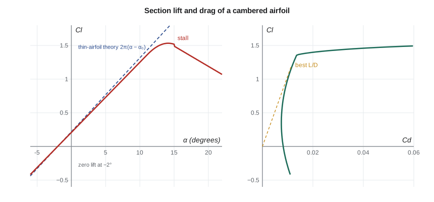
with α in radians. The lift-curve slope is 2π per radian, about 0.11 per degree, for any thin section. Camber shifts the curve: \(\alpha_{L0}\) is the zero-lift angle, which is zero for a symmetric section and negative for a cambered one, about −2° for a NACA 2412. Real airfoils follow the theory closely up to about 10° or so; their measured slope is a little below 2π, and drag coefficients at low angles are about 0.006 to 0.012, dominated by skin friction. The ratio of lift to drag can exceed 100 for a good section at its best angle.
Stall
As the angle of attack grows, the pressure on the upper surface falls further near the leading edge and then must recover over the rest of the chord. The adverse pressure gradient eventually separates the boundary layer, starting at the trailing edge for thick sections or near the leading edge for thin ones. When separation spreads over much of the upper surface, lift stops increasing and falls, while drag rises steeply. This is stall. Most airfoils reach a maximum lift coefficient of about 1.2 to 1.7 at 12 to 16°. Flaps and slats on aircraft raise the maximum lift for takeoff and landing; on wind turbines, stall was once used deliberately to limit power in high winds, but modern machines turn their blades to control the angle of attack, which is called pitch control.
Finite wings and induced drag
A real wing has tips. Air at high pressure under the wing flows around each tip toward the low pressure on top, forming tip vortices that trail downstream. Those vortices induce a downward velocity, called downwash, over the whole wing. The wing therefore sees a flow coming from slightly above the free stream, its effective angle of attack is reduced and its lift force is tilted back. The rearward component of the tilted lift is induced drag, the price of making lift with a wing of finite span. Prandtl's lifting-line theory gives, for an elliptic distribution of lift along the span:
where \(a_0\) is the section lift slope, AR is the aspect ratio, b the span and e a span efficiency factor, equal to 1 for an elliptic loading and usually 0.8 to 0.95 for practical wings. High aspect ratio reduces induced drag, which is why gliders and long-range aircraft have long, slender wings, and why wind turbine blades are long and narrow. Winglets at the tips of airliner wings reduce the strength of the tip vortices for a given span.
# Lift: a blade section of the treatment plant's wind turbine, and finite-wing corrections
import math
p, T = 97.4e3, 273.15 + 5.0      # station pressure and a mild day
rho = p / (287.0 * T)
R, n_rpm, V = 15.0, 42.0, 9.0      # rotor radius (m), rotor speed (rpm), wind speed (m/s)
a_ind = 0.30                        # axial induction: the rotor slows the wind to V(1 - a) in the rotor plane
omega = n_rpm * 2 * math.pi / 60
print(f"Air density {rho:.3f} kg/m3; tip speed {omega*R:.1f} m/s; tip-speed ratio {omega*R/V:.1f}")
# Thin-airfoil theory for a cambered section: Cl = 2 pi (alpha - alpha_L0)
alpha_L0 = math.radians(-2.0)
for r in (5.0, 10.0, 13.5):
    Va = V * (1 - a_ind)            # axial component at the blade
    Vt = omega * r                  # rotational component (wake swirl neglected)
    W = math.hypot(Va, Vt)
    phi = math.atan2(Va, Vt)        # inflow angle from the rotor plane
    twist = {5.0: 9.0, 10.0: 3.0, 13.5: 1.0}[r]
    alpha = phi - math.radians(twist)
    Cl = 2 * math.pi * (alpha - alpha_L0)
    Cd = 0.010
    c = {5.0: 1.6, 10.0: 1.1, 13.5: 0.8}[r]
    Lp = Cl * 0.5 * rho * W**2 * c
    Dp = Cd * 0.5 * rho * W**2 * c
    # Thrust and torque components per meter of blade
    Fn = Lp * math.cos(phi) + Dp * math.sin(phi)
    Ft = Lp * math.sin(phi) - Dp * math.cos(phi)
    print(f"r = {r:4.1f} m: W = {W:5.1f} m/s, inflow {math.degrees(phi):5.1f} deg, alpha {math.degrees(alpha):4.1f} deg, "
          f"Cl {Cl:.2f}, lift {Lp:5.0f} N/m, driving force {Ft:4.0f} N/m")
# Finite wing: lift-curve slope and induced drag for an elliptic loading (span efficiency e)
a0 = 2 * math.pi
for AR in (6, 10, 20):
    e = 0.95
    a = a0 / (1 + a0 / (math.pi * e * AR))
    CL = 0.8
    CDi = CL**2 / (math.pi * e * AR)
    print(f"AR = {AR:>2}: lift slope {a:.2f} per rad ({a/a0:.0%} of 2 pi), induced drag at CL 0.8 = {CDi:.4f}, L/D with profile Cd 0.010 = {CL/(CDi+0.010):.0f}")
# Stall: beyond about 12 to 15 degrees the section separates and lift falls
print("Thin-airfoil theory holds only below stall, roughly |alpha| < 10 to 12 deg for this section")Air density 1.220 kg/m3; tip speed 66.0 m/s; tip-speed ratio 7.3 r = 5.0 m: W = 22.9 m/s, inflow 16.0 deg, alpha 7.0 deg, Cl 0.99, lift 503 N/m, driving force 134 N/m r = 10.0 m: W = 44.4 m/s, inflow 8.2 deg, alpha 5.2 deg, Cl 0.78, lift 1039 N/m, driving force 134 N/m r = 13.5 m: W = 59.7 m/s, inflow 6.1 deg, alpha 5.1 deg, Cl 0.77, lift 1346 N/m, driving force 125 N/m AR = 6: lift slope 4.65 per rad (74% of 2 pi), induced drag at CL 0.8 = 0.0357, L/D with profile Cd 0.010 = 17 AR = 10: lift slope 5.19 per rad (83% of 2 pi), induced drag at CL 0.8 = 0.0214, L/D with profile Cd 0.010 = 25 AR = 20: lift slope 5.68 per rad (90% of 2 pi), induced drag at CL 0.8 = 0.0107, L/D with profile Cd 0.010 = 39 Thin-airfoil theory holds only below stall, roughly |alpha| < 10 to 12 deg for this section
The finite-wing results show the trend clearly: a wing of aspect ratio 6 keeps only about three quarters of the section's lift slope, and its induced drag at a lift coefficient of 0.8 is more than three times its profile drag. At aspect ratio 20 the wing keeps 90 percent of the section slope and its lift-to-drag ratio more than doubles. A wind turbine blade has an aspect ratio of roughly 15 to 20, and its tip losses are handled in rotor analysis by tip-loss corrections that play the role of the finite-span correction.
Worked problem
Lift-to-drag ratio of a wing
A wing of aspect ratio 10 with e = 0.95 flies at C_L = 0.8. The section profile drag coefficient is 0.010. Find the induced drag coefficient, the total drag coefficient and the lift-to-drag ratio.
Show solution
- \[C_{D,i} = \frac{0.8^2}{\pi \times 0.95 \times 10} = \frac{0.64}{29.85} = 0.0214\]
- Total \(C_D = 0.010 + 0.0214 = 0.0314\).
- \(L/D = 0.8/0.0314 = 25\).
Answer: Induced drag is twice the profile drag here. Flying at a lower lift coefficient, by going faster, reduces induced drag, which falls with the square of C_L, while profile drag stays roughly constant; the best L/D occurs where the two are equal.
The rotating blade: velocity triangles
A blade section at radius r on a turbine rotor sees two velocities: the wind arriving along the axis and the section's own motion around the rotor. The rotor slows the wind passing through it, so the axial speed at the rotor plane is \(V(1 - a)\), where a is the axial induction factor; Lesson 12 shows that a near one third extracts the most power. The section's tangential speed is \(\omega r\). The relative velocity W and the inflow angle φ follow:
where \(\beta_t\) is the local blade twist plus pitch. Lift acts perpendicular to W and drag along it. Resolved into the rotor's directions, the components along the axis push the rotor downwind as thrust, and the components in the plane of rotation turn it and produce torque:
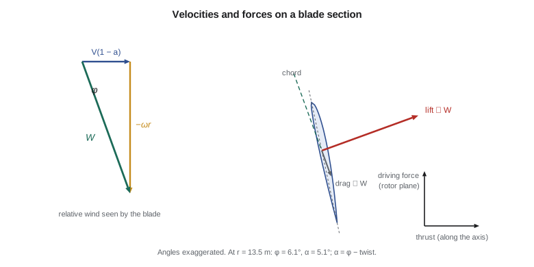
Because \(\omega r\) grows along the blade while the axial speed stays the same, the inflow angle falls toward the tip. That is why blades are twisted: the root is set at a steep angle and the tip nearly flat, so that every section works near its best angle of attack. The blade also narrows toward the tip, because the faster tip sections produce enough force with a smaller chord. The program shows the proposed turbine at its 9 m/s design wind: the tip moves at 66 m/s, a tip-speed ratio of 7.3, and the relative velocity at the 13.5 m section is about 60 m/s, more than six times the wind. Each meter of blade there produces about 1.3 kN of lift, but only about 0.12 kN of it drives the rotor; the rest is thrust that the tower must resist.
Worked problem
A section near the tip
At r = 13.5 m the proposed turbine's axial speed is 9 × 0.7 = 6.3 m/s and the section moves at 59.4 m/s. The local twist is 1° and the section's zero-lift angle is −2°. Find the inflow angle, angle of attack and lift coefficient.
Show solution
- \(\tan\phi = 6.3/59.4 = 0.106\), so φ = 6.1°.
- α = 6.1 − 1.0 = 5.1°.
- \(C_l = 2\pi\,(5.1 + 2.0)\pi/180 = 2\pi \times 0.124 = 0.78\).
Answer: The section works at a moderate lift coefficient, well below stall, with an angle of attack of about 5°. If the wind rose to 14 m/s at the same rotor speed, φ would increase to about 9.4° and α to 8.4°, still below stall; the controller would then begin pitching the blades to hold the power at its rated value.
Lift in other machines
The same ideas describe many machines in a water utility. The blades of axial-flow pumps and propeller turbines are airfoils in water; their velocity triangles are drawn exactly as for the wind turbine, and their designers use cascade data for rows of closely spaced airfoils, which interfere with each other. Fan blades in the filter gallery's air handling units are airfoil-shaped for efficiency. Mixers in the flocculation basins use hydrofoil impellers that move water with less power than flat paddles. In water, lift also brings cavitation: the low pressure on the suction side of a hydrofoil can fall below the vapor pressure, and Lesson 11 returns to that problem in pumps.
In the United States, larger wind turbines are generally certified to the IEC 61400 series of standards, and small turbines are often certified to a separate national small wind turbine standard. Their installation must meet the National Electrical Code, local zoning and, near airports, Federal Aviation Administration notification rules, and interconnection requires approval from the electric utility serving the site.
Common mistakes
MistakeExplaining lift by equal transit time over the top and bottom.
InsteadLift comes from the pressure difference produced by the flow's circulation; upper-surface particles arrive first.
MistakeUsing the section lift slope 2π for a finite wing.
InsteadCorrect the slope for aspect ratio; a wing of AR 6 keeps only about three quarters of it.
MistakeUsing thin-airfoil theory beyond stall.
InsteadThe linear relation fails once the upper-surface boundary layer separates, near 12 to 16°.
MistakeMeasuring the blade's inflow angle from the axis.
InsteadIn these formulas φ is measured from the plane of rotation.
MistakeAssuming all of a blade's lift produces torque.
InsteadMost of it is thrust; only the component in the rotor plane drives the rotor.
Summary and key terms
- Lift is the force component perpendicular to the flow, F_L = C_L ½ρV²S.
- An airfoil's sharp trailing edge sets its circulation through the Kutta condition, and lift follows from L′ = ρVΓ.
- Thin-airfoil theory gives C_l = 2π(α − α_L0); real sections follow it until stall near 12 to 16°.
- Finite wings lose lift slope and pay induced drag C_Di = C_L²/(πe AR); high aspect ratio reduces both effects.
- A turbine blade section sees the vector sum of the slowed wind V(1 − a) and its own motion ωr.
- Blades are twisted because the inflow angle falls toward the tip; most of the lift becomes thrust, not torque.
- Lift
- The component of fluid force perpendicular to the approaching flow.
- Airfoil
- A streamlined section designed to produce lift with little drag.
- Angle of attack
- The angle between the chord line and the approaching flow.
- Camber
- The curvature of the airfoil mean line.
- Kutta condition
- The requirement that flow leave a sharp trailing edge smoothly, which fixes the circulation.
- Stall
- Loss of lift caused by extensive boundary-layer separation at high angle of attack.
- Aspect ratio
- Span squared divided by planform area.
- Induced drag
- Drag caused by the downwash of trailing tip vortices on a finite wing.
- Tip-speed ratio
- The ratio of blade tip speed to wind speed.
- Axial induction factor
- The fractional reduction of wind speed at the rotor plane.
Practice problems
Work each problem on paper first, then reveal the answer to check.
A thin symmetric airfoil is at 4°. Find C_l.
Show answer
2π × 0.0698 ≈ 0.44.
A wing of 10 m span and 12.5 m² area flies at C_L = 0.6 with e = 0.9. Find AR and C_Di.
Show answer
AR = 8; C_Di = 0.36/(π × 0.9 × 8) ≈ 0.016.
Find the lift per meter of a 1.2 m chord section at C_l = 1.0 in a 40 m/s relative wind with ρ = 1.2 kg/m³.
Show answer
1,152 N/m.
A rotor of 15 m radius turns at 42 rpm in a 9 m/s wind. Find the tip-speed ratio.
Show answer
66.0/9 = 7.3.
In the program, raise the wind speed to 12 m/s. What happens to the angle of attack at r = 13.5 m?
Show answer
It rises to about 7.0°; the section is still below stall.
Why are the blade root sections thick and the tip sections thin?
Show answer
The root carries the largest bending moment and needs strength; the fast tip sections need efficiency.
Lesson quiz · 5 questions
Score 60% or more to complete this lesson.
Create a free account to save your progress, take quizzes and earn a certificate.