
MEC-360 · Lesson 12 of 12 · 24 min
Springs, welded machine parts and the capstone drive train
The last weeks of Owen's term bring the two projects together. The PC-150 sludge pump goes to the utility as a complete package: a 7.5 kW motor, the GR-5 reducer, the pump itself, a relief valve that protects the progressive cavity pump if a downstream valve is closed, and a welded steel baseplate with a motor bracket. Farah asks Owen to finish two remaining elements, the relief valve spring and the welds on the motor bracket, and then to prepare the design review package for the whole drive train. This lesson covers helical springs and welded joints in machine parts, and then walks through the capstone review, which uses every lesson in the course.
Helical compression springs
A helical compression spring is a wire wound into a helix. When it is compressed, the wire is loaded mainly in torsion, with a smaller direct shear. The key dimensions are the wire diameter d, the mean coil diameter D and the number of active coils \(N_a\); the spring index \(C = D/d\), usually between 4 and 12, describes how tightly the wire is wound. The shear stress at the inside of the coil, where it is highest, is
where \(K_B\) is the Bergsträsser factor, which accounts for direct shear and the curvature of the wire; the older Wahl factor gives nearly the same values. The spring rate follows from the torsional deflection of the wire:
with G the shear modulus, about 79.3 GPa (11.5 Mpsi) for spring steels. Spring wire is much stronger than ordinary steel because cold drawing to a small diameter work-hardens it; its tensile strength rises as the diameter falls, following \(S_{ut} = A/d^m\), with constants tabulated for each wire type. For music wire, A ≈ 2,211 MPa·mm^m and m ≈ 0.145. The torsional yield strength is about 0.45 \(S_{ut}\) for music wire and cold-drawn carbon steel, before any presetting.
Designing the relief valve spring
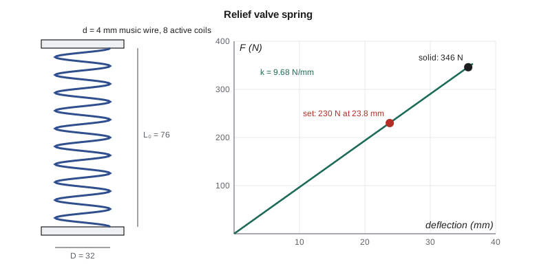
The PC-150's relief valve must start to open at its set pressure, which requires a spring force of 230 N on the valve disc, and must be able to open a further 12 mm without the spring going solid. A good spring design rule is that the stress at the solid length should not exceed the torsional yield strength, so that a spring compressed solid by accident does not take a permanent set. Owen tries music wire 4 mm in diameter wound to a 32 mm mean diameter with 8 active coils and squared and ground ends.
# Capstone checks for the PC-150 drive: relief-valve spring, motor-base fillet welds, output shaft and key
import math
# 1. Helical compression spring for the relief valve (music wire, squared and ground ends)
d, D, Na, G = 4.0, 32.0, 8, 79.3e3            # mm, mm, active coils, MPa
Sut = 2211 * d ** -0.145                       # MPa, music wire (A/d^m)
Ssy = 0.45 * Sut
C = D / d
KB = (4 * C + 2) / (4 * C - 3)                 # Bergstrasser factor
k = d**4 * G / (8 * D**3 * Na)                 # N/mm
F_set = 230.0                                  # N, cracking force at the set pressure
tau_set = KB * 8 * F_set * D / (math.pi * d**3)
Nt = Na + 2; Ls = d * Nt                       # total coils and solid length
y_set = F_set / k
F_solid = k * (y_set + 12.0)                   # if the valve can travel 12 mm beyond the set point to solid
tau_solid = KB * 8 * F_solid * D / (math.pi * d**3)
print(f"spring index C = {C:.1f}, KB = {KB:.3f}, rate k = {k:.2f} N/mm")
print(f"Sut = {Sut:.0f} MPa, Ssy = {Ssy:.0f} MPa")
print(f"at set: deflection {y_set:.1f} mm, stress {tau_set:.0f} MPa; at solid: {tau_solid:.0f} MPa -> n = {Ssy/tau_solid:.2f}")
L0 = Ls + y_set + 12.0
print(f"free length about {L0:.0f} mm, slenderness L0/D = {L0/D:.2f}")

# 2. Motor-base bracket: two 6 mm fillet welds, each 100 mm long, 80 mm apart, load 3 kN at 150 mm
h, Lw, b, Fw, e = 6.0, 100.0, 80.0, 3000.0, 150.0
A = 2 * 0.707 * h * Lw
Ju = Lw * (3 * b**2 + Lw**2) / 6               # unit polar moment of two parallel lines
J = 0.707 * h * Ju
tau1 = Fw / A
rmax = math.hypot(b / 2, Lw / 2)
tau2 = Fw * e * rmax / J
cos_t = (b / 2) / rmax
tau = math.sqrt((tau1 + tau2 * cos_t) ** 2 + (tau2 * math.sqrt(1 - cos_t**2)) ** 2)
print(f"\nweld: primary {tau1:.1f} MPa, secondary {tau2:.1f} MPa, resultant {tau:.1f} MPa")
print(f"E49xx (E70xx) electrode allowable shear 0.30 x 490 = {0.30*490:.0f} MPa -> n = {0.30*490/tau:.1f}")

# 3. Reducer output shaft at the gear seat: 172 N.m torque, gear loads from Lesson 8, midway between bearings 120 mm apart
T = 171.8; Wt, Wr = 1507.0, 549.0
Mx = math.hypot(Wt, Wr) / 2 * 0.060              # moment at the gear (simply supported)
Se, Sut_s, Kf, Kfs, n = 178e6, 630e6, 1.8, 1.5, 2.0   # keyway at the gear seat raises Kf
dmin = (16 * n / math.pi * (2 * Kf * Mx / Se + math.sqrt(3) * Kfs * T / Sut_s)) ** (1 / 3)
print(f"\noutput shaft: M = {Mx:.0f} N.m, DE-Goodman diameter {dmin*1000:.1f} mm -> 35 mm seat")
Fk = T / 0.0175; Lk = 0.040
print(f"10 x 8 mm key, 40 mm long: shear n = {0.577*370e6/(Fk/(0.010*Lk)):.1f}, crushing n = {370e6/(Fk/(0.004*Lk)):.1f}")spring index C = 8.0, KB = 1.172, rate k = 9.68 N/mm Sut = 1808 MPa, Ssy = 814 MPa at set: deflection 23.8 mm, stress 343 MPa; at solid: 517 MPa -> n = 1.57 free length about 76 mm, slenderness L0/D = 2.37 weld: primary 3.5 MPa, secondary 14.0 MPa, resultant 16.4 MPa E49xx (E70xx) electrode allowable shear 0.30 x 490 = 147 MPa -> n = 9.0 output shaft: M = 48 N.m, DE-Goodman diameter 25.8 mm -> 35 mm seat 10 x 8 mm key, 40 mm long: shear n = 8.7, crushing n = 6.0
Worked problem
Relief valve spring
Find the spring rate, the deflection and stress at the set force, the stress when the valve is fully open and the spring is solid, and the free length.
Show solution
- \(C = 32/4 = 8\); \(K_B = (32 + 2)/(32 - 3) = 1.172\).
- \[k = \frac{4^4 \times 79\,300}{8 \times 32^3 \times 8} = 9.68\ \text{N/mm}, \qquad y_{\text{set}} = \frac{230}{9.68} = 23.8\ \text{mm}\]
- \[\tau_{\text{set}} = 1.172\frac{8(230)(32)}{\pi(4)^3} = 343\ \text{MPa}\]
- At solid, the deflection is 23.8 + 12 = 35.8 mm, the force 346 N and the stress 517 MPa. For 4 mm music wire, \(S_{ut} = 2211/4^{0.145} = 1808\) MPa and \(S_{sy} = 0.45 \times 1808 = 814\) MPa, so the factor of safety at solid is 1.57.
- Total coils \(N_t = N_a + 2 = 10\); solid length \(L_s = dN_t = 40\) mm; free length \(L_0 = 40 + 35.8 = 76\) mm.
Answer: The spring is safe at solid, and its slenderness \(L_0/D = 2.37\) is well below the buckling limit for a spring compressed between parallel plates. A relief valve spring sees few cycles, so static strength governs. A spring that cycles continuously, such as a valve spring in an engine or a mechanical seal spring, needs a fatigue check using the alternating and mean shear stresses and torsional endurance data for spring wire, with shot peening often used to raise its fatigue strength.
Springs have other design details: the ends (plain, squared, ground) change the number of inactive coils and the solid length; the spring must fit in its bore and over its guide with clearance for the diameter increase under compression; and the natural frequency of the spring itself must be well above any forcing frequency, or the coils will surge. Extension springs, torsion springs, Belleville washers and wave springs each have their own formulas, built on the same ideas of stress, rate and material strength.
Welded joints in machine parts
The motor bracket on the PC-150 baseplate is a steel plate welded to the frame with two fillet welds, one on each side. A fillet weld is a triangular bead joining two surfaces at right angles; its size is the leg length h, and its strength is based on the throat, the smallest section through the weld, which is \(0.707h\) for an equal-leg weld. Fillet welds are assumed to fail in shear on the throat, whatever the direction of the load. For a weld group loaded eccentrically in its own plane, the load produces a direct (primary) shear and a torsional (secondary) shear about the weld group's centroid:
where \(J_u\) is the unit polar second moment of the weld lines treated as lines, tabulated for common patterns, and r is the distance from the centroid to the point of interest. The two shear components are added as vectors, and the largest resultant is usually at the weld end farthest from the centroid.
Worked problem
Motor bracket welds
Two 6 mm fillet welds, each 100 mm long and 80 mm apart, carry 3 kN at an eccentricity of 150 mm. Find the largest shear stress in the welds.
Show solution
- Throat area \(A = 2 \times 0.707 \times 6 \times 100 = 848\) mm²; primary shear \(\tau' = 3000/848 = 3.5\) MPa.
- For two parallel lines of length d spaced b apart, \(J_u = d(3b^2 + d^2)/6 = 4.87 \times 10^5\) mm³, so \(J = 0.707 \times 6 \times J_u = 2.06 \times 10^6\) mm⁴.
- At the weld end, \(r = \sqrt{40^2 + 50^2} = 64.0\) mm and \(\tau'' = 3000 \times 150 \times 64.0/(2.06 \times 10^6) = 14.0\) MPa.
- Adding the vectors gives a resultant of 16.4 MPa.
Answer: Against an allowable shear on the throat of 0.30 times the electrode's tensile strength, the factor of safety is about 9. Static strength is no problem. The bracket carries the motor's vibration, though, and welds are notoriously poor in fatigue because the weld toe is a sharp notch with tensile residual stress. For fatigue, welded details are rated by category curves from standards rather than by the static method, and good practice keeps welds out of the highest-stressed regions and grinds the toes of critical welds.
In the United States, AWS D1.1 governs structural steel welding, and the allowable shear on a fillet weld throat is 0.30 times the electrode's tensile strength, so an E70xx electrode (70 ksi) gives 21 ksi. In US units the motor bracket welds are 1/4 in fillets about 4 in long, the resultant stress is about 2.4 ksi, and the factor of safety against the 21 ksi allowable is about 9. Weld fatigue categories are given in AISC 360 Appendix 3 and AWS D1.1.
The capstone: design review of the PC-150 drive train
Owen's design review package for the PC-150 drive brings together the checks from every lesson. Each element is listed with its governing requirement, the method used, the result and the margin. Farah's rule is that the review must show not only that each element passes, but which check governs it and why, so that anyone changing the design later knows what to recheck.
| Element | Governing check | Lesson | Result |
|---|---|---|---|
| Overall | Reliability of series system; seals and bearings dominate | 1 | Bearing and seal choices drive reliability |
| Reducer output shaft, 35 mm seat | DE-Goodman fatigue at the keyed gear seat (minimum 25.8 mm) | 3, 4, 5 | n well above 2; sized up for stiffness and common bearings |
| Output shaft key, 10 × 8 × 40 mm | Crushing on the hub side | 5 | n = 6.0 |
| Output shaft bearings, 6207 | L10 life against 20,000 h with application factor 1.2 | 6 | About 880,000 h at 417 rpm; ample margin |
| Gear stage (helical, 45 mm face, 300 HB) | Pitting resistance of the gear | 9, 10 | S_H ≈ 1.37 for the spur equivalent; helical higher |
| Two-stage option for 105 rpm | Train value and stage ratios | 10 | 17/71 × 19/76 gives 105.4 rpm |
| Casing and reducer cover bolts | Separation and fatigue | 11 | Separation factor above 4 |
| Relief valve spring | Stress at solid against torsional yield | 12 | n = 1.57 |
| Motor bracket welds | Throat shear, fatigue detail | 12 | n ≈ 9 static; toe ground |
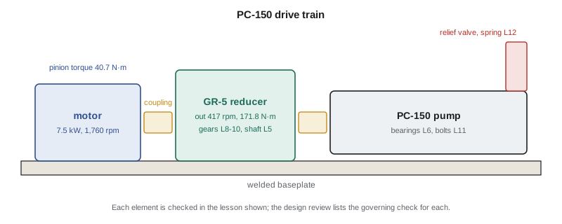
The review also records the assumptions that, if they change, would invalidate a check. The output shaft check assumes the pump's starting torque is no more than 1.5 times the running torque; progressive cavity pumps can need high breakaway torque with thick sludge, so the motor's soft starter is set to limit it. The bearing life assumes clean oil; the reducer has a breather with a filter. The gear rating assumes the oil temperature stays below about 80 °C; a temperature switch trips the motor if it does not. Recording such assumptions is part of the engineer's responsibility described in Lesson 1, and it is the main thing a reviewer looks for.
Finally, the review compares the design with the specification line by line: power, speed, noise, service life, maintainability, cost and the safety requirements for guarding and pressure protection. Owen's package passes, with two actions: confirm the soft-starter setting with the utility's electrical engineer, and order a sample of the relief valve springs for a load test before production. Farah signs the review, and Owen's co-op term ends with a design that will be built.
Common mistakes
MistakeUsing the uncorrected stress 8FD/(πd³) for a spring.
InsteadInclude the Bergsträsser or Wahl factor for curvature and direct shear.
MistakeForgetting to check a spring at its solid length.
InsteadMake the stress at solid no more than the torsional yield strength, or limit travel.
MistakeUsing the leg size instead of the throat for fillet weld stress.
InsteadThe throat is 0.707h for an equal-leg fillet.
MistakeChecking welds for static strength only in a vibrating machine.
InsteadUse fatigue category data for welded details.
MistakePresenting a design review without the assumptions behind it.
InsteadRecord the loads and conditions each check depends on.
Summary and key terms
- Helical spring stress is τ = K_B·8FD/(πd³) and the rate k = d⁴G/(8D³N_a); spring wire strength rises as diameter falls.
- The relief valve spring (4 mm music wire, D = 32 mm, 8 active coils) has k = 9.68 N/mm and a factor of 1.57 at solid.
- Fillet welds are designed on the throat, 0.707h; eccentric loads add primary and secondary shear vectorially.
- The motor bracket welds see 16.4 MPa, a static factor of about 9; fatigue detail governs welded machine parts.
- A design review lists each element's governing check, result, margin and the assumptions behind it.
- The PC-150 drive train passes with recorded actions on starting torque and spring testing.
- Spring index
- C = D/d, the ratio of mean coil diameter to wire diameter.
- Bergsträsser factor
- A stress correction factor for direct shear and curvature in a helical spring.
- Spring rate
- The force per unit deflection of a spring.
- Solid length
- The length of a compression spring with all coils touching.
- Squared and ground ends
- Spring ends closed and ground flat to sit squarely on a seat.
- Fillet weld
- A triangular weld joining two surfaces at an angle, usually 90°.
- Throat
- The smallest section through a fillet weld, 0.707 times the leg size for equal legs.
- Primary shear
- The direct shear in a weld group from the applied force.
- Design review
- A formal check of a design against its specification, with its assumptions recorded.
Practice problems
Work each problem on paper first, then reveal the answer to check.
A spring has d = 3 mm, D = 24 mm and N_a = 10, with G = 79.3 GPa. Find its rate.
Show answer
About 5.81 N/mm.
For the same spring with F = 100 N, find K_B and the shear stress.
Show answer
K_B = 1.172; τ = 265 MPa.
Find S_ut and S_sy for 3 mm music wire.
Show answer
S_ut ≈ 1,885 MPa; S_sy ≈ 848 MPa.
A single 8 mm fillet weld 120 mm long carries 10 kN in direct shear. Find the throat shear stress.
Show answer
About 14.7 MPa.
In the program, change the relief valve spring to 10 active coils. What are the new rate and set deflection?
Show answer
k = 7.75 N/mm; y = 29.7 mm.
Why must a design review record its assumptions?
Show answer
A later change to a load or condition may invalidate a check, and the record shows what to recheck.
Lesson quiz · 5 questions
Score 60% or more to complete this lesson.
Create a free account to save your progress, take quizzes and earn a certificate.