
MEC-360 · Lesson 10 of 12 · 24 min
Helical, bevel and worm gears and gear trains
The spur version of the GR-5 works, but the utility's specification limits noise in its pump rooms, and spur gears at nearly 5 m/s are noisy. Farah asks Owen to compare a helical version. The same week, two other jobs arrive: a mixer drive that turns the motor's power through a right angle, and a valve actuator that must hold its position when the motor stops. Each needs a different kind of gear, and the sludge pump itself, it turns out, should run even slower than 417 rpm. This lesson covers helical gears, bevel gears, worm gears and the trains that combine gears to reach large ratios.
Helical gears
Helical gears have teeth cut at an angle, the helix angle \(\psi\), to the axis of the gear. Contact between mating teeth starts at one end of a tooth and spreads across the face as the gears turn, instead of along the whole face at once as in spur gears. Load is picked up and released gradually, and more teeth share the load at any moment, so helical gears run more quietly and smoothly and carry more load for the same size. The price is an axial thrust force that the bearings must carry, and slightly higher sliding losses. Helix angles are typically 15° to 30°. Mating helical gears on parallel shafts have equal helix angles of opposite hand.
Helical geometry is described in two planes. The normal plane is perpendicular to the teeth; the transverse plane is perpendicular to the axis. The cutting tool works in the normal plane, so the normal module \(m_n\) and normal pressure angle \(\phi_n\) are the standard values. In the transverse plane:
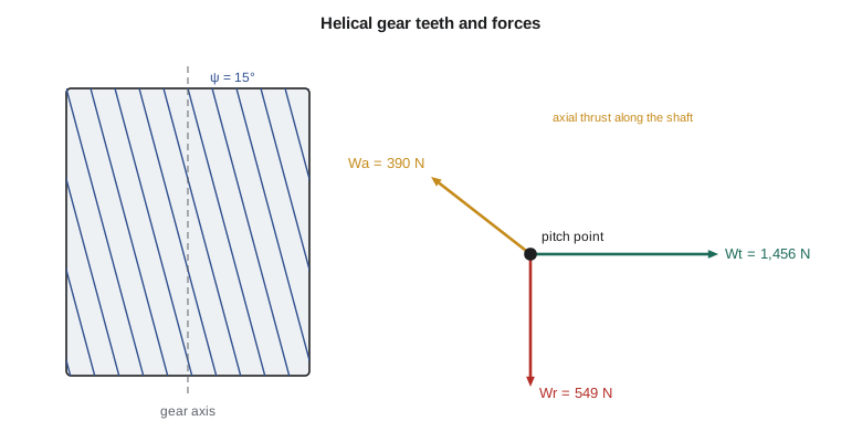
The face contact ratio, or overlap ratio, \(m_F = F\tan\psi/(\pi m_n)\), measures how far a tooth's contact advances across the face; a value of at least 1 is recommended for smooth running. Helical gear forces resolve into three components:
Worked problem
A helical GR-5
Owen keeps the GR-5's tooth numbers (18 and 76), uses a normal module of 3 mm, a normal pressure angle of 20° and a helix angle of 15°. Find the pitch diameters, shaft spacing and forces for 7.5 kW at 1,760 rpm.
Show solution
- \[m_t = \frac{3}{\cos 15°} = 3.106\ \text{mm}, \qquad d_P = 55.9\ \text{mm}, \qquad d_G = 236.0\ \text{mm}, \qquad C = 146.0\ \text{mm}\]
- \[\phi_t = \arctan\frac{\tan 20°}{\cos 15°} = 20.65°\]
- Pinion torque 40.7 N·m gives \(W_t = 2(40.7)/0.0559 = 1456\) N, \(W_r = 549\) N and \(W_a = 1456\tan 15° = 390\) N.
- With a 36 mm face, the overlap ratio is \(36\tan 15°/(3\pi) = 1.02\).
Answer: The helical option needs a slightly larger housing (146 mm between shafts instead of 141 mm) unless the tooth numbers or helix angle are adjusted, and its bearings must take 390 N of thrust. In return it is quieter and, by AGMA rating, carries roughly 20 to 30 percent more load. Owen chooses a helix angle and tooth numbers that keep the original shaft spacing, a common design exercise, and the helical version becomes the production design.
Double helical (herringbone) gears cancel the thrust by using two opposite-hand helices side by side; they are used in large turbine and mill drives. Crossed helical gears on non-parallel shafts make point contact and carry only light loads.
Bevel gears
Bevel gears transmit power between intersecting shafts, usually at 90°. Their pitch surfaces are cones that roll on each other, with the cone apexes meeting at the intersection of the shaft axes. The pitch angle of the pinion is \(\gamma = \arctan(N_P/N_G)\) for a 90° pair. Straight bevel gears have straight teeth tapering toward the apex; spiral bevel gears have curved, oblique teeth that run more smoothly and are used where speed or load is high; hypoid gears, as in vehicle axles, have offset axes. Forces are calculated at the mean radius of the face, \(r_{av} = d_P/2 - (F/2)\sin\gamma\), and the radial and axial components on the pinion are
For the mixer drive, a 20-tooth pinion of module 4 mm drives a 40-tooth gear, and the pinion carries 120 N·m. The program gives a pitch angle of 26.6°, a mean radius of 34.4 mm and a tangential load of 3,487 N, with 1,135 N radial and 568 N axial on the pinion. Bevel pinions are often overhung, and their bearings must locate them accurately along the axis, because the mesh is sensitive to axial position.
Worm gears
A worm gear set has a screw-like worm meshing with a worm wheel on a shaft at 90° to it. One revolution of a single-start worm advances the wheel by one tooth, so ratios of 10 to 100 are easy in a single stage. The lead angle \(\lambda\) of the worm is the angle of its thread relative to a plane perpendicular to its axis. Contact is mostly sliding, so friction is significant and efficiency depends strongly on the lead angle and the coefficient of friction f:
Small lead angles give low efficiency but can make the drive self-locking: the wheel cannot drive the worm backwards if the static coefficient of friction satisfies \(f \ge \cos\phi_n\tan\lambda\). Self-locking is useful for hoists and valve actuators, where the load must hold when the motor stops, although vibration can reduce friction and cause creep, so a separate brake is still used where safety depends on it. Worm wheels are usually bronze, running against a hardened steel worm, and heat generation often limits the rating rather than strength.
Worked problem
Valve actuator worm
For a valve actuator, compare lead angles of 3.5°, 6° and 12° with a running friction coefficient of 0.05, a static coefficient of 0.10 and \(\phi_n = 20°\).
Show solution
- The program gives running efficiencies of 53, 66 and 79 percent.
- Self-locking requires \(0.10 \ge \cos 20° \tan\lambda\): \(\tan 3.5° \times 0.94 = 0.057\), yes; \(\tan 6° \times 0.94 = 0.099\), just; \(\tan 12° \times 0.94 = 0.200\), no.
Answer: A 6° lead angle is on the edge of self-locking. Tidewater chooses 3.5° for the valve actuator, accepting the lower efficiency because the actuator runs only a few minutes a day and must hold the valve against the line pressure.
Gear trains
A gear train combines several meshes. Its train value e is the ratio of output speed to input speed, the product of the driving tooth numbers divided by the product of the driven tooth numbers:
with the sign positive if input and output turn the same way. In a simple train, each shaft carries one gear and idlers change only the direction. In a compound train, some shafts carry two gears, so large ratios fit in a compact space. A single stage is usually limited to a ratio of about 6 to 8 for spur and helical gears, because the pinion becomes too small or the gear too large.
The sludge pump's process engineer now asks for about 105 rpm, a ratio of about 16.7, too much for one stage. A two-stage compound train with 17 and 71 teeth in the first stage and 19 and 76 in the second gives e = (17 × 19)/(71 × 76) = 0.05986, an output of 105.4 rpm. Choosing tooth numbers for a required ratio is a small search problem: the program shows the result, and a few lines of code can test all combinations within limits on tooth numbers.
# Helical, bevel and worm gear forces, and gear train values
import math
P, n1 = 7500.0, 1760
T1 = P / (2 * math.pi * n1 / 60)
# Helical replacement for the GR-5 stage: same ratio, normal module 3 mm, helix angle chosen for a near-equal spacing
mn, phin, psi = 3.0, math.radians(20), math.radians(15)
Np, Ng = 18, 76
mt = mn / math.cos(psi)
dp = mt * Np; dg = mt * Ng
phit = math.atan(math.tan(phin) / math.cos(psi))
Wt = 2 * T1 / (dp / 1000)
print(f"helical: transverse module {mt:.3f} mm, pitch diameters {dp:.1f} / {dg:.1f} mm, shaft spacing {(dp+dg)/2:.1f} mm")
print(f"transverse pressure angle {math.degrees(phit):.2f} deg; Wt = {Wt:.0f} N, Wr = {Wt*math.tan(phit):.0f} N, thrust Wa = {Wt*math.tan(psi):.0f} N")
F = 36.0
print(f"axial contact ratio for a {F:.0f} mm face: {F*math.tan(psi)/(math.pi*mn):.2f}")

# Straight bevel pair turning the drive through 90 degrees (mixer drive), forces at the mean radius
Npb, Ngb, mb, Fb = 20, 40, 4.0, 25.0
gam = math.atan(Npb / Ngb)
dpb = mb * Npb; rav = dpb / 2 - Fb / 2 * math.sin(gam)
Wtb = 120.0 / (rav / 1000)
print(f"\nbevel pinion pitch angle {math.degrees(gam):.1f} deg, mean radius {rav:.1f} mm, Wt = {Wtb:.0f} N")
print(f"pinion radial load {Wtb*math.tan(math.radians(20))*math.cos(gam):.0f} N, pinion thrust {Wtb*math.tan(math.radians(20))*math.sin(gam):.0f} N")

# Worm drive for a valve actuator: running efficiency and self-locking at rest
phin_w, f_run, f_static = math.radians(20), 0.05, 0.10
for lam_deg in (3.5, 6.0, 12.0):
    lam = math.radians(lam_deg)
    eff = (math.cos(phin_w) - f_run * math.tan(lam)) / (math.cos(phin_w) + f_run / math.tan(lam))
    locks = f_static >= math.cos(phin_w) * math.tan(lam)
    print(f"lead angle {lam_deg:4.1f} deg: running efficiency {eff:.1%}, {'self-locking at rest' if locks else 'can back-drive'}")

# Compound train for the PC-150 sludge pump: target 1760 -> about 105 rpm
pairs = [(17, 71), (19, 76)]
e = 1.0
for a, b in pairs: e *= a / b
print(f"\ncompound train value e = {e:.5f}, output {n1*e:.1f} rpm, overall ratio {1/e:.2f}")
# Planetary stage (sun driven, ring fixed, carrier output): Willis equation
Ns, Nr = 21, 63
print(f"planetary: sun {Ns}, ring {Nr}, planets {(Nr-Ns)//2}; ratio sun/carrier = {1 + Nr/Ns:.2f}")helical: transverse module 3.106 mm, pitch diameters 55.9 / 236.0 mm, shaft spacing 146.0 mm transverse pressure angle 20.65 deg; Wt = 1456 N, Wr = 549 N, thrust Wa = 390 N axial contact ratio for a 36 mm face: 1.02 bevel pinion pitch angle 26.6 deg, mean radius 34.4 mm, Wt = 3487 N pinion radial load 1135 N, pinion thrust 568 N lead angle 3.5 deg: running efficiency 53.3%, self-locking at rest lead angle 6.0 deg: running efficiency 66.0%, self-locking at rest lead angle 12.0 deg: running efficiency 79.1%, can back-drive compound train value e = 0.05986, output 105.4 rpm, overall ratio 16.71 planetary: sun 21, ring 63, planets 21; ratio sun/carrier = 4.00
Planetary trains
In a planetary (epicyclic) train, one or more planet gears mesh with a central sun gear and an internal ring gear, and the planets are carried on an arm called the carrier. With one member held, the train gives a fixed ratio; with all three free, it can add or split speeds, as in a vehicle differential. Analysis uses the relative motion of the gears with respect to the carrier, often written as the Willis equation:
where e is the train value with the carrier held. With the ring fixed and the sun driving, the ratio is \(1 + N_R/N_S\). For a sun of 21 teeth and a ring of 63, the ratio is 4.0, and the planets have (63 − 21)/2 = 21 teeth. Because the load is shared among several planets, planetary gearboxes are compact and carry high torques; they are common in mixers, wind turbines and the large sludge pumps Tidewater buys from specialist makers.
In US units, the helical GR-5 has a normal diametral pitch near 8.5 (the nearest standard is 8), a thrust of about 88 lbf and a tangential load of about 327 lbf. US gear reducer makers rate their products to AGMA 6013 and related application standards, which set service factors for driven machinery; a progressive cavity sludge pump typically needs a service factor of about 1.25 to 1.5.
Common mistakes
MistakeUsing the normal module in d = mN for a helical gear.
InsteadUse the transverse module m_t = m_n/cos ψ.
MistakeForgetting the axial thrust of helical and bevel gears.
InsteadInclude W_a in the bearing selection and shaft design.
MistakeRelying on worm self-locking as the only brake where safety depends on it.
InsteadVibration can reduce friction; add a brake where a falling load is a hazard.
MistakeGetting the sign of a train value wrong.
InsteadCount external meshes: each reverses direction; internal meshes do not.
MistakePutting too large a ratio in one stage.
InsteadSplit ratios above about 6 to 8 into two or more stages.
Summary and key terms
- Helical gears run quieter and carry more load than spur gears but produce axial thrust W_a = W_t tan ψ.
- Transverse module and pressure angle follow from the normal values: m_t = m_n/cos ψ, tan φ_t = tan φ_n/cos ψ.
- Bevel gears connect intersecting shafts; forces are found at the mean cone radius.
- Worm gears give large single-stage ratios with sliding contact; low lead angles can be self-locking but are inefficient.
- Train values multiply; the GR-5 two-stage train with 17/71 and 19/76 teeth gives 105.4 rpm.
- Planetary trains share load among planets; with a fixed ring, the ratio is 1 + N_R/N_S.
- Helix angle
- The angle between a helical tooth and the gear axis.
- Normal module
- The module measured in the plane perpendicular to the teeth.
- Overlap ratio
- For helical gears, F tan ψ/(πm_n), the axial overlap of tooth contact.
- Bevel gear
- A gear with a conical pitch surface for intersecting shafts.
- Lead angle
- The angle of a worm thread measured from a plane perpendicular to the worm axis.
- Self-locking
- A drive that cannot be driven backwards from its output.
- Train value
- The ratio of output speed to input speed of a gear train.
- Compound gear train
- A train in which some shafts carry two gears.
- Planetary gear train
- A train with planet gears on a rotating carrier meshing with a sun and a ring.
Practice problems
Work each problem on paper first, then reveal the answer to check.
A helical gear has m_n = 4 mm, ψ = 20° and 40 teeth. Find its pitch diameter.
Show answer
170.3 mm.
For W_t = 2 kN, φ_n = 20° and ψ = 25°, find W_r and W_a.
Show answer
W_r = 803 N; W_a = 933 N.
A worm with λ = 10° runs with f = 0.04 and φ_n = 20°. Find its efficiency.
Show answer
About 80 percent.
Find the train value of a compound train with drivers of 20 and 18 teeth and driven gears of 60 and 72 teeth.
Show answer
e = 1/12.
A planetary set has a 24-tooth sun and a 72-tooth ring. With the ring fixed, find the ratio and the planet tooth number.
Show answer
Ratio 4.0; planets 24 teeth.
Why are worm wheels usually bronze?
Show answer
Bronze against hardened steel resists scuffing and wear under the high sliding of worm contact.
Lesson quiz · 5 questions
Score 60% or more to complete this lesson.
Create a free account to save your progress, take quizzes and earn a certificate.