
MEC-360 · Lesson 1 of 12 · 27 min
The machine design process, factors of safety and reliability
Tidewater Pump Works in Portland has built end-suction centrifugal pumps for water utilities, food plants and pulp mills for more than forty years. Owen Clarke, who drew the BB-210 bearing bracket during his first co-op term, is back for his third, this time in the design group. Farah Siddiqui, the senior design engineer, has given him a real job: help her design the power end of the new TP-80 pump, an 11 kW (15 hp) unit driven by a four-pole motor at 1,760 rpm. The power end is everything that carries the impeller and transmits the torque: the shaft, the bearings, the bearing frame, the seals, the coupling and the bolts that hold it together. Later in the term the same team will design a small spur gear reducer, the GR-5, for a progressive cavity sludge pump. This course follows both projects. Each lesson takes one family of machine elements, explains how it fails, and shows how to size it so that it does not.
Machine design is different from the analysis courses that came before it. In statics and mechanics of materials the geometry was given and the stress was the answer. In design the stress limit is given and the geometry is the answer, and there are always more unknowns than equations. A shaft diameter, a bearing size and a bolt grade all interact, so the designer must make reasonable choices, check them, and change them when a check fails. The skill is in making good first choices and knowing which check is likely to govern.
The design process
Most design processes follow the same loop, whatever the textbook calls the stages. The need is recognized, usually as a customer request or a market gap. The problem is defined in a specification that sets measurable requirements. Concepts are generated and compared. The chosen concept is analyzed and sized. The design is checked by calculation, simulation and test, documented in drawings and models, and released for manufacture. At every stage the designer may have to go back: a failed check sends the work back to sizing, and a failed test may send it back to the concept.
For the TP-80, the specification Farah wrote with the sales team includes a duty point of 90 m³/h at 32 m head (about 400 US gpm at 105 ft), a maximum working pressure of 16 bar (230 psi), a bearing life of at least 17,500 hours, a shaft deflection at the seal faces of no more than 50 µm (0.002 in) at the worst operating point, and interchangeability with the impellers and casings of the older TP-75. Each of these requirements becomes a check in later lessons. Some come from customers, some from the company's experience, and some from industry standards for process pumps, which set limits on deflection, bearing life and dimensions so that pumps from different makers can be swapped on the same baseplate.
A good specification states what the machine must do, not how. 'Shaft deflection at the seal faces not to exceed 50 µm' is a requirement; 'use a 40 mm shaft' is a solution. Writing requirements in terms of function leaves room for better solutions and makes it clear what each check must show.
Codes, standards and the designer's responsibility
Machine elements are among the most standardized parts in engineering. Bearings, keys, threads, bolts, gears, springs and couplings are made to international and national standards, and their ratings are calculated by methods published by bodies such as ISO, ASME, AGMA and the bearing makers. The designer's job is rarely to invent a new element; it is to choose the right standard element, size it correctly and arrange it so that the loads it sees are the loads it was rated for.
In the United States, a product such as the TP-80 is not normally required to carry a professional engineer's seal, but Tidewater's chief engineer in Portland is licensed by the Maine State Board of Licensure for Professional Engineers, and the company follows the engineering practice that license implies. Product liability law makes the manufacturer responsible for a reasonably safe design, and OSHA's machine guarding rules, together with the ANSI B11 family of machine safety standards, govern guards for exposed shafts and couplings. Pressure-containing parts may fall under the ASME Boiler and Pressure Vessel Code.
Standards also carry hard-won experience. A rule such as 'limit seal-face deflection to 50 µm' exists because pumps with more deflection wore out their mechanical seals quickly. When a standard sets a limit, the designer should understand the failure it prevents, because that understanding is what allows a sensible decision when a case falls outside the standard.
Factor of safety and design factor
No calculation predicts a part's strength or its loads exactly. Material strength varies from heat to heat, dimensions vary within tolerances, loads vary with operating conditions, and the models used to calculate stress are approximations. The traditional way to cover all of this is a factor of safety: the ratio of a strength to the corresponding stress.
The two forms are the same only when stress is proportional to load, which it is in most linear elastic problems but not, for example, in a preloaded bolt or a buckling column. Engineers distinguish the design factor \(n_d\), the value chosen before the part is sized, from the factor of safety \(n\), the value actually achieved after rounding to standard sizes. Rounding a 34.5 mm calculated diameter up to a 35 mm bearing seat raises the factor of safety slightly above the design factor; that is the normal situation.
Choosing a design factor is a judgment based on the consequences of failure and the quality of the information. A useful way to think about it is to ask four questions. How well is the material strength known? How well are the loads known? How good is the stress model? How serious is a failure? Where every answer is good, as in a well-tested aircraft part with a known load spectrum, factors near 1.25 to 1.5 are used. Where loads are poorly known or failure is dangerous, factors of 3 or more are common. For the TP-80 shaft, Farah sets a design factor of 2 against fatigue and checks that yielding under the largest transient load is far less likely.
| Situation | Typical design factor | Comment |
|---|---|---|
| Reliable materials, well-known loads, failure not hazardous | 1.25 to 1.5 | Weight-critical structures with extensive testing |
| Average materials and loads, ordinary machinery | 1.5 to 2.5 | Most pump, conveyor and gear designs |
| Poorly known loads or material, or shock | 2.5 to 4 | Crushers, early prototypes |
| Failure endangers people, or brittle materials | 3 to 6 or more | Often set by a code or standard |
Reliability: a statistical view of safety
A factor of safety hides an important question: how likely is the part to fail? Two shafts with the same factor of safety can have very different failure probabilities if one has a much wider scatter of strength or load. The reliability approach treats strength \(S\) and stress \(\sigma\) as random variables. If both are normally distributed, their difference \(m = S - \sigma\), the margin, is also normal, and failure happens when \(m < 0\). The standardized distance from the mean margin to zero is
where \(\hat\sigma\) is a standard deviation and \(\Phi\) the standard normal cumulative distribution. A value of z = 3 gives a reliability of 0.99865, about 1.3 failures per thousand; z = 4.75 gives about one per million. The calculation is called the stress-strength interference model, because failures come from the region where the tail of the stress distribution overlaps the tail of the strength distribution.
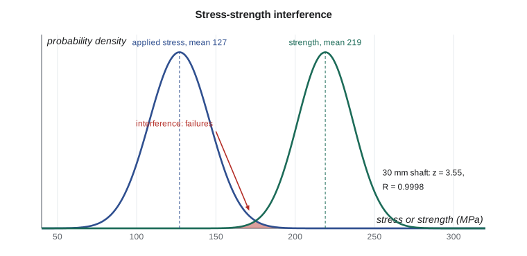
The program below applies the model to the TP-80 shaft. The fatigue strength of the shaft steel at the bearing shoulder has a mean of about 219 MPa with 8 percent scatter, and the alternating stress from the overhung impeller varies by about 15 percent with flow rate and hydraulic unbalance. It compares the 35 mm shaft with a lighter 30 mm alternative that a cost review suggested.
# Design factor, factor of safety and reliability for the TP-80 pump shaft
import math
def Phi(z):                      # standard normal cumulative probability
    return 0.5 * (1 + math.erf(z / math.sqrt(2)))

# Deterministic check: yield strength against the largest static stress (Lesson 2)
Sy = 530.0                        # MPa, cold-drawn 1045 steel (typical handbook value)
sigma_vm = 89.2                   # MPa, von Mises stress at the inboard bearing shoulder
print(f"deterministic factor of safety against yield n = {Sy/sigma_vm:.2f}")

# Stochastic check: fatigue strength and alternating stress treated as normal variables
mu_S, cov_S = 219.0, 0.08         # endurance strength at 50 % reliability, 8 % scatter
for d, mu_s in ((35, 80.0), (30, 127.0)):     # alternating stress in the 35 mm and a lighter 30 mm shaft
    s_S, s_s = cov_S * mu_S, 0.15 * mu_s      # 15 % scatter in the hydraulic load
    z = (mu_S - mu_s) / math.sqrt(s_S**2 + s_s**2)
    R = Phi(z)
    print(f"{d} mm shaft: mean factor {mu_S/mu_s:.2f}, z = {z:.2f}, R = {R:.6f}, "
          f"about {(1-R)*1e6:.3g} failures per million shafts")

# What mean design factor is needed for a target reliability?
for target in (0.99, 0.999, 0.9999, 0.999999):
    lo, hi = 1.0, 10.0
    for _ in range(80):
        nd = (lo + hi) / 2
        zz = (nd - 1) / math.sqrt((0.08 * nd)**2 + 0.15**2)   # stress mean set to 1
        lo, hi = (lo, nd) if Phi(zz) > target else (nd, hi)
    print(f"target R = {target:<9} -> mean design factor about {nd:.2f}")

# Components in series: the pump fails if any one of them fails
parts = {"shaft": 0.9999, "inboard bearing": 0.95, "outboard bearing": 0.95,
         "mechanical seal": 0.90, "coupling": 0.995}
R_sys = math.prod(parts.values())
print(f"\nsystem reliability over the design life = {R_sys:.4f}")
for k, v in parts.items():
print(f" {k:17s} {v:.4f} share of the unreliability {(1-v)/sum(1-x for x in parts.values()):5.1%}")deterministic factor of safety against yield n = 5.94 35 mm shaft: mean factor 2.74, z = 6.55, R = 1.000000, about 2.96e-05 failures per million shafts 30 mm shaft: mean factor 1.72, z = 3.55, R = 0.999811, about 189 failures per million shafts target R = 0.99 -> mean design factor about 1.44 target R = 0.999 -> mean design factor about 1.61 target R = 0.9999 -> mean design factor about 1.77 target R = 0.999999 -> mean design factor about 2.06 system reliability over the design life = 0.8081 shaft 0.9999 share of the unreliability 0.0% inboard bearing 0.9500 share of the unreliability 24.4% outboard bearing 0.9500 share of the unreliability 24.4% mechanical seal 0.9000 share of the unreliability 48.8% coupling 0.9950 share of the unreliability 2.4%
Worked problem
Reliability of the lighter shaft
The 30 mm shaft has a mean alternating stress of 127 MPa with a 15 percent coefficient of variation. The fatigue strength has a mean of 219 MPa with an 8 percent coefficient of variation. Find the reliability.
Show solution
- Standard deviations: \(\hat\sigma_S = 0.08 \times 219 = 17.5\) MPa; \(\hat\sigma_\sigma = 0.15 \times 127 = 19.1\) MPa.
- \[z = \frac{219 - 127}{\sqrt{17.5^2 + 19.1^2}} = \frac{92}{25.9} = 3.55\]
- From the normal table or the program, \(R = \Phi(3.55) = 0.99981\).
Answer: About 190 shafts in every million would fail in fatigue, even though the mean factor of safety is 1.72. The 35 mm shaft has z = 6.55 and a failure rate too small to matter. Farah keeps the 35 mm shaft: the saving of a few hundred grams of steel is not worth a warranty problem.
The same model explains why a fixed design factor gives different reliabilities for different materials. If strength scatter is small and loads are well known, a factor of 1.5 might give six-nines reliability; with wide scatter, a factor of 2 might give only three nines. The program's third section finds the mean design factor needed for several reliability targets with the scatter assumed here. It also shows why the normal model must be used with care: real distributions often have heavier tails than the normal curve, and the tails are exactly where failures come from. Lognormal and Weibull distributions are often better choices for fatigue strength and bearing life, and Lesson 6 uses the Weibull form for bearings.
Reliability of systems
A pump fails when any one of its essential parts fails. For components in series in this reliability sense, and assuming independent failures, the system reliability is the product of the component reliabilities:
The last part of the program applies this to the TP-80 over its design life. A shaft with 0.9999 reliability, two bearings each at 0.95, a mechanical seal at 0.90 and a coupling at 0.995 give a system reliability of only 0.81. Half of the unreliability comes from the seal, a quarter from each bearing, and almost none from the shaft. This is typical of pumps: field data from many plants show seals and bearings as the leading causes of repair, and shaft fractures as rare. The lesson for the designer is to spend effort where the unreliability is. A heavier shaft that reduces deflection at the seal faces may improve system reliability far more through longer seal life than through any change in shaft fatigue.
Worked problem
Effect of a better seal
Replacing the seal with a cartridge seal of reliability 0.95 over the same life raises the system reliability to what?
Show solution
- \(R = 0.9999 \times 0.95 \times 0.95 \times 0.95 \times 0.995 = 0.853\).
Answer: The system reliability rises from 0.81 to 0.85. To go further, the bearings must also improve, for example by choosing bearings with a longer rated life so that their reliability over 17,500 hours is higher, which is the subject of Lesson 6.
Units, tolerances and preferred sizes
Machine design uses a mixture of units. In SI, stresses are in megapascals (N/mm²), lengths in millimeters, forces in newtons or kilonewtons and torques in newton-meters. In US customary practice, stresses are in kpsi (ksi), lengths in inches, forces in pounds-force and torques in pound-force inches or feet. Tidewater sells into both markets, so its drawings use metric dimensions with inch equivalents where customers need them, and its bearings, keys and metric fasteners are all ISO standard parts. A useful habit is to work an entire calculation in one consistent set of units and convert only the final answers.
US practice still uses inch dimensions for many shafts, keys and fasteners, while rolling bearings are almost all metric worldwide. Conversions: 1 MPa = 145.0 psi, 1 kN = 224.8 lbf, 1 N·m = 0.7376 lbf·ft, 1 in = 25.4 mm. The TP-80's 35 mm bearing seat is 1.378 in, and its 59.7 N·m running torque is 44.0 lbf·ft or 528 lbf·in.
Rounding to standard sizes is not just convenience. Standard parts are cheaper, available, and tested; a special bearing or a non-standard key costs more and may take weeks to replace in the field. A design that uses standard elements in standard ways is easier to maintain, which for a pump that will run for twenty years is a large part of its value.
Common mistakes
MistakeQuoting a factor of safety without saying which failure mode it refers to.
InsteadState the mode: n = 5.9 against yielding, n = 2.1 against fatigue.
MistakeUsing the same design factor for every material and load.
InsteadChoose the factor from the uncertainty in strength, load and model, and the consequence of failure.
MistakeWriting a specification that prescribes a solution.
InsteadSpecify the function and limit, such as a maximum deflection, and let the design meet it.
MistakeTreating a high factor of safety as proof that a part cannot fail.
InsteadScatter matters; use the interference model or test data to estimate reliability.
MistakeImproving the most reliable part of a system.
InsteadSystem reliability is a product; improve the weakest components first.
Summary and key terms
- Machine design sizes elements to meet requirements; there are more unknowns than equations, so the process is iterative.
- A good specification states measurable functions and limits, many of which come from industry standards.
- The design factor is chosen from the uncertainty in strength, loads and models and the consequences of failure; the factor of safety is the value achieved.
- The stress-strength interference model converts mean values and scatter into a reliability through z = (μ_S − μ_σ)/√(σ̂_S² + σ̂_σ²).
- The lighter 30 mm TP-80 shaft would have a reliability of about 0.9998; the 35 mm shaft is effectively free of fatigue failures.
- For components in series, system reliability is the product of component reliabilities, so seals and bearings dominate pump reliability.
- Specification
- A document stating the measurable requirements a design must meet.
- Design factor
- The factor of safety chosen before sizing a part.
- Factor of safety
- The ratio of strength to stress, or failure load to applied load, actually achieved.
- Reliability
- The probability that a part or system performs without failure over a stated life.
- Interference model
- A reliability model in which failure occurs where the stress distribution overlaps the strength distribution.
- Coefficient of variation
- The standard deviation divided by the mean.
- Series system
- A system that fails if any one of its components fails.
- Power end
- The shaft, bearings, frame and seals that carry the impeller and transmit torque in a pump.
- Preferred number
- A standard size chosen from a geometric series to limit the number of sizes in use.
Practice problems
Work each problem on paper first, then reveal the answer to check.
A part has a yield strength of 350 MPa and a von Mises stress of 140 MPa. Find the factor of safety against yielding.
Show answer
2.5.
Strength has mean 400 MPa and standard deviation 30 MPa; stress has mean 250 MPa and standard deviation 25 MPa. Find z and R.
Show answer
z = 3.84; R ≈ 0.99994.
Four components with reliabilities 0.99, 0.98, 0.95 and 0.999 act in series. Find the system reliability.
Show answer
About 0.921.
In the program, change the stress scatter to 25 percent. What happens to the reliability of the 30 mm shaft?
Show answer
z drops to about 2.5 and R to about 0.994.
Why is a load-based factor of safety misleading for a preloaded bolt?
Show answer
Bolt stress is not proportional to the external load because of the preload, so the two ratios differ.
Convert the TP-80 power and speed to US units and find the torque in lbf·in.
Show answer
14.75 hp at 1,760 rpm gives about 528 lbf·in.
Lesson quiz · 5 questions
Score 60% or more to complete this lesson.
Create a free account to save your progress, take quizzes and earn a certificate.