
MEC-330 · Lesson 8 of 12 · 25 min
Vapor-compression refrigeration and heat pumps
Northgate's owners see a business beyond heating. Several downtown office towers, a hotel, a data center and Riverside General Hospital cool their buildings with their own rooftop units and chillers, and some of that equipment is near the end of its life. A district cooling loop, distributing chilled water at about 6 °C from a central plant, could serve them more efficiently and free roof space. In winter, the same thinking runs the other way: a large heat pump could take heat from the treated effluent of the wastewater plant next door and lift it into the district system. Both machines run on the vapor-compression cycle introduced at the end of Thermodynamics I. This lesson analyzes it in depth, with the losses of real machines, multistage and cascade arrangements, and the choice of refrigerant under today's rules.
Refrigerators and heat pumps
A refrigerator removes heat \(Q_L\) from a cold space and rejects \(Q_H\) to warm surroundings using work input \(W\); a heat pump does the same thing for the sake of \(Q_H\). Their coefficients of performance are
For reversible machines between reservoirs at \(T_L\) and \(T_H\), the Carnot limits are \(T_L/(T_H - T_L)\) and \(T_H/(T_H - T_L)\). Both fall rapidly as the temperature lift \(T_H - T_L\) grows, which is the most important fact in refrigeration engineering: every degree of unnecessary lift costs energy.
The ideal vapor-compression cycle
The reversed Carnot cycle cannot be built with real equipment for the same reasons as the Carnot power cycle: compressing a wet mixture and expanding a liquid in a turbine are impractical. The ideal vapor-compression cycle makes two changes. The refrigerant is evaporated completely before the compressor, so the compressor handles only vapor, and the expansion turbine is replaced by a throttling valve, which is cheap and simple. The four processes are (1-2) isentropic compression of saturated vapor to the condenser pressure, (2-3) constant-pressure heat rejection in the condenser to saturated liquid, (3-4) throttling to the evaporator pressure at constant enthalpy, and (4-1) constant-pressure heat absorption in the evaporator.
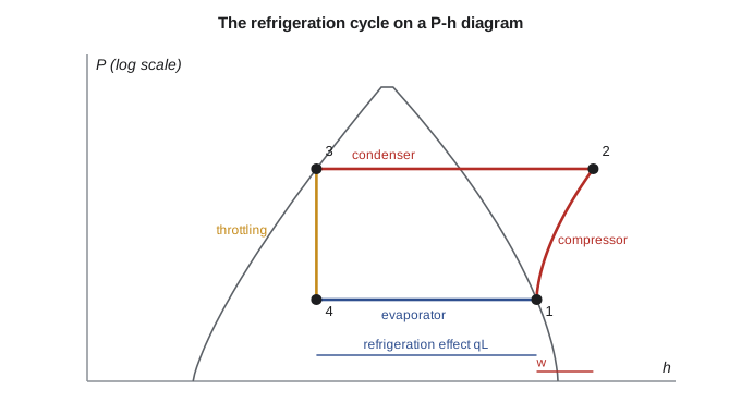
Refrigeration engineers plot the cycle on a pressure-enthalpy (P-h) diagram, on which three of the four processes are straight lines and the heat and work are horizontal distances. Throttling is a vertical line. The throttling process is the cycle's main irreversibility: the liquid flashes partly to vapor as it drops in pressure, and that flash gas has absorbed heat from the remaining liquid without producing work. The superheated discharge is the second: the refrigerant leaves the compressor hotter than the condensing temperature and rejects heat across a larger temperature difference than a Carnot cycle would.
A district cooling chiller
Kofi sizes the first chiller at 3500 kW of cooling, about 1000 tons of refrigeration. Chilled water returns from the buildings at about 13 °C and leaves at 6 °C; the refrigerant evaporates at about 0 °C. A cooling tower supplies condenser water at 24 to 29 °C, and the refrigerant condenses at 0.8 MPa (31.3 °C). For the calculation the team uses R-134a, whose properties are well tabulated; a new chiller would use a lower-GWP refrigerant, discussed below, with very similar cycle behavior.
# District cooling chiller (R-134a reference data) and heat pump estimates for Northgate
def interp(x, x1, y1, x2, y2): return y1 + (x - x1) * (y2 - y1) / (x2 - x1)

# R-134a, rounded from standard tables: evaporator 0 C (293 kPa), condenser 0.8 MPa (31.31 C)
h1, s1 = 250.45, 0.93139                     # saturated (quality 1) at 0 C
hg8, sg8 = 267.29, 0.91835                   # saturated (quality 1) at 0.8 MPa
h40, s40 = 276.45, 0.94798                   # superheated, 0.8 MPa and 40 C
hf8 = 95.47                                  # saturated liquid at 0.8 MPa
hf26 = 87.83                                 # liquid subcooled to 26 C (approximated by saturated liquid at 26 C)

h2s = interp(s1, sg8, hg8, s40, h40)
T2s = interp(s1, sg8, 31.31, s40, 40.0)
for label, eta_c, h3 in (("ideal", 1.0, hf8), ("actual", 0.75, hf26)):
    w = (h2s - h1) / eta_c
    qL = h1 - h3                             # throttling: h4 = h3
    print(f"{label:6s}: compressor exit h = {h1 + w:6.2f}, w = {w:5.2f}, qL = {qL:6.2f} kJ/kg, COP_R = {qL / w:.2f}")
print(f"isentropic discharge temperature about {T2s:.1f} C; Carnot COP_R = {273.15 / (31.31 - 0):.2f}")

Q_chill = 3500.0                             # kW, about 1000 tons of refrigeration
w = (h2s - h1) / 0.75; qL = h1 - hf26
m = Q_chill / qL
print(f"\n3500 kW chiller: refrigerant {m:.1f} kg/s, compressor {m * w:.0f} kW, heat to cooling tower {m * (qL + w):.0f} kW")

# Heat pumps: COP_HP from a fraction of the Carnot value, for a 10 C effluent source
print("\nheat pump from 10 C effluent (5 K approaches, 50 % of Carnot)")
for T_supply in (50, 70, 90):
    TL, TH = 10 - 5 + 273.15, T_supply + 5 + 273.15
    cop = 0.5 * TH / (TH - TL)
    print(f"  supply {T_supply} C: COP_HP = {cop:.2f}")

# Two-stage cascade: overall COP_R from the stage COPs (heat rejected by the low stage = heat absorbed by the high stage)
def cascade(c1, c2): return c1 * c2 / (1 + c1 + c2)
c_low, c_high = 2.8, 3.5
print(f"\ncascade: low stage COP {c_low}, high stage COP {c_high} -> overall COP_R = {cascade(c_low, c_high):.2f}")

# Direct emissions from leakage: CO2-equivalent per year for a 600 kg charge, 2 % annual leak rate
for name, gwp in (("R-134a", 1430), ("R-513A", 631), ("R-1234ze(E)", 7), ("R-717 (ammonia)", 0)):
print(f" {name:16s} GWP {gwp:5d}: {600 * 0.02 * gwp / 1000:6.2f} t CO2e per year")ideal : compressor exit h = 271.32, w = 20.87, qL = 154.98 kJ/kg, COP_R = 7.43 actual: compressor exit h = 278.28, w = 27.83, qL = 162.62 kJ/kg, COP_R = 5.84 isentropic discharge temperature about 35.1 C; Carnot COP_R = 8.72 3500 kW chiller: refrigerant 21.5 kg/s, compressor 599 kW, heat to cooling tower 4099 kW heat pump from 10 C effluent (5 K approaches, 50 % of Carnot) supply 50 C: COP_HP = 3.28 supply 70 C: COP_HP = 2.49 supply 90 C: COP_HP = 2.05 cascade: low stage COP 2.8, high stage COP 3.5 -> overall COP_R = 1.34 R-134a GWP 1430: 17.16 t CO2e per year R-513A GWP 631: 7.57 t CO2e per year R-1234ze(E) GWP 7: 0.08 t CO2e per year R-717 (ammonia) GWP 0: 0.00 t CO2e per year
Worked problem
The ideal and actual chiller cycle
R-134a evaporates at 0 °C (\(h_1 = 250.45\), \(s_1 = 0.93139\)) and condenses at 0.8 MPa. At 0.8 MPa, saturated vapor has \(h = 267.29\), \(s = 0.91835\), superheated vapor at 40 °C has \(h = 276.45\), \(s = 0.94798\), and saturated liquid has \(h = 95.47\). Find the ideal COP. Then find the actual COP with a compressor isentropic efficiency of 0.75 and liquid subcooled to 26 °C (\(h_3 = 87.83\)).
Show solution
- Isentropic discharge by interpolation at \(s = 0.93139\): \(h_{2s} = 267.29 + \frac{0.93139 - 0.91835}{0.94798 - 0.91835}(276.45 - 267.29) = 271.32\) kJ/kg, about 35 °C.
- Ideal: \(w = 271.32 - 250.45 = 20.87\); \(q_L = 250.45 - 95.47 = 154.98\); \(\text{COP}_R = 7.43\).
- Actual: \(w = 20.87/0.75 = 27.83\) kJ/kg; \(q_L = 250.45 - 87.83 = 162.62\) kJ/kg.
- \[\text{COP}_R = \frac{162.62}{27.83} = 5.84\]
Answer: The Carnot limit between 0 and 31.3 °C is 8.72; the ideal cycle reaches 85 percent of it and the actual cycle 67 percent. Subcooling helps by reducing flash gas; compressor inefficiency hurts much more. For 3500 kW the refrigerant flow is 21.5 kg/s, the compressor draws about 600 kW, and the condenser rejects about 4.1 MW to the cooling tower.
Real chillers depart from even this actual cycle. The evaporator and condenser need temperature differences to drive heat transfer, so the refrigerant evaporates a few degrees below the leaving chilled-water temperature and condenses a few degrees above the leaving condenser-water temperature. Pressure drops in the piping, heat gains in the suction line and the superheat needed to protect the compressor from liquid all cost a little. Large centrifugal chillers reach full-load COPs of about 6 to 7 at standard rating conditions, and better at part load with cooler condenser water.
The program's results show why district cooling can beat building-by-building chillers. A central plant uses a few large, efficient machines run near their best operating points, can use the coldest condenser water available, and can add thermal storage, for example chilling water at night when electricity is cheap. In Minneapolis's climate, from late autumn to spring the outdoor air or the river is cold enough to cool the chilled-water loop with little or no compressor work, which is called free cooling.
Heat pumps for the district
A heat pump is a refrigerator run for its hot side. The sewer heat pump from Thermodynamics I lifts heat from wastewater effluent, which stays near 10 °C even in a Minneapolis winter. The program estimates heat pump COPs using a common rule of thumb: a well-designed machine reaches about half the Carnot COP between its evaporating and condensing temperatures. With 5 K approaches in each heat exchanger, the COP falls from 3.3 for a 50 °C supply to 2.5 for 70 °C and 2.0 for 90 °C. Every reduction in supply temperature pays off directly in COP, which is why district systems built around heat pumps use hot water at 50 to 70 °C rather than steam.
Worked problem
Heat pump COP and supply temperature
A heat pump takes heat from effluent at 10 °C and delivers hot water at 70 °C. With 5 K approaches, it evaporates at 5 °C and condenses at 75 °C. If it reaches half the Carnot COP, find its COP and the electricity needed for 5 MW of heat.
Show solution
- \(T_L = 278.15\) K; \(T_H = 348.15\) K.
- Carnot: \(\text{COP}_{HP} = 348.15/70 = 4.97\).
- \[\text{COP}_{HP} = 0.5(4.97) = 2.49 \qquad \dot W = \frac{5000}{2.49} = 2010\ \text{kW}\]
Answer: About 2 MW of electricity gives 5 MW of heat, 3 MW of it taken from the effluent. If the network could run at 50 °C instead, the same heat would need about 1.5 MW. At Northgate, where the network is steam at 180 °C, a heat pump would have to feed a hot-water extension of the network or preheat boiler feedwater and district return water rather than make steam directly.
Multistage and cascade systems
When the temperature lift is large, a single compressor runs at a high pressure ratio with poor efficiency and a very hot discharge. Two-stage compression with intercooling between stages lowers the work, and a flash chamber between stages separates the vapor formed by throttling to the intermediate pressure so that only liquid continues to the evaporator. Cascade systems use two separate circuits, often with different refrigerants, linked by a heat exchanger that is the condenser of the low-temperature circuit and the evaporator of the high-temperature circuit. Each refrigerant can then work at pressures that suit it. Cascades are used for very low temperatures and for high-lift heat pumps.
If the low stage has \(\text{COP}_1\) and the high stage \(\text{COP}_2\), and all the heat rejected by the low stage is absorbed by the high stage, the overall COP of the cascade is
For stage COPs of 2.8 and 3.5, the program finds 1.34. A cascade is less efficient than either stage alone, because the high stage must also pump the low stage's compressor work, but it can reach lifts that a single stage cannot handle.
Choosing a refrigerant
A refrigerant should have a saturation pressure at the evaporator temperature a little above atmospheric (so air does not leak in), a reasonable condensing pressure, a large latent heat, low toxicity and flammability, chemical stability, and low environmental impact. Chlorofluorocarbons such as R-12 met all but the last of these and were phased out under the Montreal Protocol because they destroy stratospheric ozone. Their hydrofluorocarbon replacements, such as R-134a and R-410A, do not harm ozone but are strong greenhouse gases, and the 2016 Kigali Amendment commits most countries to phasing down their use.
| Refrigerant | Type | Approximate GWP (100-year) | Safety class | Typical uses |
|---|---|---|---|---|
| R-134a | HFC | 1430 | A1 | Older chillers, car air conditioning |
| R-410A | HFC blend | 2088 | A1 | Older unitary air conditioning and heat pumps |
| R-513A | HFC/HFO blend | about 630 | A1 | Retrofits and new chillers |
| R-1234ze(E) | HFO | under 10 | A2L | Centrifugal and screw chillers, heat pumps |
| R-32 | HFC | 675 | A2L | Unitary air conditioning and heat pumps |
| R-717 (ammonia) | Natural | 0 | B2L | Industrial refrigeration, large heat pumps |
| R-744 (carbon dioxide) | Natural | 1 | A1 | Supermarkets, high-temperature water heating |
| R-290 (propane) | Natural | 3 | A3 | Small charges, some heat pumps |
In the United States, the AIM Act gives EPA authority to phase down HFC production and to restrict high-GWP refrigerants by equipment type. EPA's Technology Transitions rule set a GWP limit of 700 for many new chillers starting in 2025, which rules out R-134a; EPA has since proposed and made revisions, so designers work from the current version of the rule. R-513A, R-1234ze(E), R-514A or ammonia would qualify for a new Northgate chiller. Section 608 of the Clean Air Act governs refrigerant handling and technician certification.
The last block of the program shows what is at stake. A 600 kg charge leaking 2 percent a year releases about 17 metric tons of CO2-equivalent annually with R-134a, under 8 metric tons with R-513A and almost nothing with an HFO or ammonia. Indirect emissions from the electricity the chiller uses are often larger still, so a refrigerant that costs a few percent in efficiency can be a poor trade. Carbon dioxide is especially interesting for heat pumps: its critical temperature is only 31 °C, so in heat pump service it rejects heat above the critical point in a gas cooler, with a gliding temperature that matches heating water from 10 to 90 °C very well.
In US practice, refrigeration capacity is quoted in tons (1 ton = 12,000 Btu/h = 3.517 kW) and chiller efficiency as kW per ton, where lower is better: a COP of 5.84 is 3.517/5.84 = 0.60 kW/ton. Unitary equipment is rated by EER (Btu/h per watt; EER = 3.412 × COP) and seasonal ratings such as SEER2 and HSPF2. Northgate's 3500 kW chiller is about 1000 tons, and in English units its refrigerant flow is about 171,000 lbm/h.
Common mistakes
MistakeTreating the expansion valve as isentropic.
InsteadThrottling is isenthalpic: h₄ = h₃, and entropy rises.
MistakeUsing COP_HP = COP_R for a heat pump.
InsteadCOP_HP = COP_R + 1 for the same cycle.
MistakeIgnoring heat-exchanger approach temperatures.
InsteadThe refrigerant must evaporate below and condense above the fluid temperatures; this widens the lift.
MistakeChoosing a refrigerant on efficiency alone.
InsteadGWP, safety class, pressure and regulations all matter.
MistakeExpecting a cascade to beat a single stage.
InsteadA cascade's overall COP is lower than either stage's; it is chosen for large lifts.
Summary and key terms
- COP_R = Q_L/W and COP_HP = Q_H/W = COP_R + 1; both fall rapidly as the temperature lift grows.
- Ideal vapor-compression cycle: isentropic compression, condensation, throttling (h₄ = h₃), evaporation.
- Throttling and superheated discharge are the main irreversibilities of the ideal cycle; compressor inefficiency dominates real ones.
- Subcooling raises the refrigeration effect; lower lift raises COP.
- Heat pumps reach roughly half of Carnot; lower supply temperatures raise their COP.
- Multistage and cascade systems handle large lifts.
- Refrigerant choice is constrained by GWP limits, safety class and pressures.
- Coefficient of performance
- The ratio of useful heat removed (refrigerator) or delivered (heat pump) to work input.
- Vapor-compression cycle
- The refrigeration cycle of compressor, condenser, expansion valve and evaporator.
- Refrigeration effect
- The heat absorbed per unit mass of refrigerant in the evaporator.
- Flash gas
- Vapor formed when liquid refrigerant is throttled to a lower pressure.
- Subcooling
- Cooling the condensed liquid below its saturation temperature.
- Temperature lift
- The difference between the condensing and evaporating temperatures.
- Cascade system
- Two refrigeration circuits linked by a heat exchanger, each with its own refrigerant.
- Free cooling
- Cooling a chilled-water loop with cold outdoor air or water without running compressors.
- Global warming potential
- The warming effect of a gas relative to the same mass of carbon dioxide over a stated period, usually 100 years.
- Gas cooler
- The high-side heat exchanger of a transcritical carbon dioxide cycle, where heat is rejected above the critical point.
Practice problems
Work each problem on paper first, then reveal the answer to check.
A refrigerator has a COP_R of 4.2. What is its COP as a heat pump?
Show answer
5.2.
Find the Carnot COP_R between −10 °C and 35 °C.
Show answer
5.85.
In the actual chiller cycle, what is the compressor discharge enthalpy?
Show answer
About 278.3 kJ/kg.
In the program, raise the compressor efficiency to 0.85. What is the actual COP_R?
Show answer
About 6.62.
A cascade has stage COPs of 3.0 and 3.0. Find the overall COP.
Show answer
1.29.
Convert a chiller COP of 6.5 to kW/ton.
Show answer
0.54 kW/ton.
Lesson quiz · 5 questions
Score 60% or more to complete this lesson.
Create a free account to save your progress, take quizzes and earn a certificate.