
LVT-230 · Lesson 5 of 12 · 19 min
Access control architecture
Every access-controlled door works the same way at the moment someone presents a card: the reader reads it, a controller decides, the lock releases, the door opens and closes, and the event is recorded. What differs from building to building is how the parts are arranged behind that door: where the decision is made, how the controllers talk to the server, what happens when the network goes down, and how the system grows. Those choices decide how reliable the system is and how hard it is to install and service. This lesson covers the parts of an access control system and how they connect, the main architectures, the inputs and outputs at a door, and how Sanjay's design for Juniper Point and Riverside school is laid out.
The parts of the system
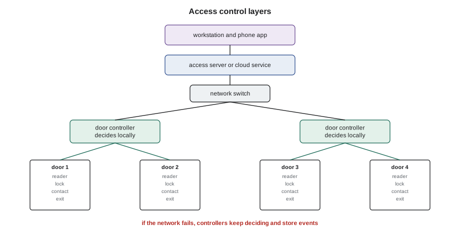
An access control system has four layers. At the door are the field devices: the reader, the electric lock, the door position switch, the request-to-exit device, and sometimes a sounder or an intercom. Above or near the door is the door controller, sometimes called the panel or the field controller, which connects to the field devices, holds a copy of the access rules and makes the decision. Behind the controllers is the server or cloud service that runs the access control software, holds the master database of people, credentials, doors and schedules, and sends updates to the controllers. And at the top are the clients: the workstations, browsers and phone apps where the owner's staff manage the system and watch events.
Most decisions are made at the controller, not the server. When a card is presented, the controller checks its local copy of the database and releases the lock within a fraction of a second. It then reports the event to the server. That design means the doors keep working if the network or the server goes down: the controllers carry on with their last copy of the rules and store events until the connection comes back. A design in which every decision goes to the server and back is slower and stops working when the connection fails, and is avoided for doors that matter.
Architectures
Access control systems are arranged in a few common ways, and a job may mix them.
In the traditional panel-based design, a multi-door controller in a telecommunications room or a security closet serves several doors, often two to eight, with a home-run cable from the controller to each door's devices. The panels connect to each other and to the server over the network or over an RS-485 serial bus. This is robust, easy to service in one place and common in schools and hospitals.
In an edge or door-mounted design, a small controller at each door, often powered by Power over Ethernet, connects to the network directly. It needs only one network cable to the door, plus short cables to the devices, which suits renovations where pulling home runs to a central room is hard. Lock power may come from the PoE controller itself, within its PoE budget, or from a local supply.
In a cloud-hosted design, the server is a service run by the manufacturer or the integrator on the internet. The controllers at the site connect outward to the service, and the owner manages the system through a browser or app. The controllers still make local decisions. Cloud systems suit owners without an IT department to run a server, like many condo corporations, but they depend on the internet connection for management and event reporting and raise questions about where the data is stored that the owner must answer.
Wireless and offline locks are another option. Battery-powered locks with built-in readers communicate with the system over a low-power radio link, or are updated by the credentials themselves. They avoid cabling a door completely, which makes them popular for interior doors such as offices and the Juniper Point amenity rooms, but they need batteries changed, and their status may be reported less often than a wired door.
| Architecture | Where the controller is | Cabling to the door | Suits |
|---|---|---|---|
| Panel-based | In a TR or security closet | Home run from panel to each door | New buildings, schools, hospitals |
| Edge, PoE | At or above each door | One network cable plus short local cables | Renovations, scattered doors |
| Cloud-hosted | Local controllers, server online | Either of the above | Owners without servers, multi-site |
| Wireless locks | In the lock, linked by radio | None to the door | Interior doors, retrofits |
Juniper Point is a cloud-hosted panel-based system: three two-door controllers in the security closet on P1 serve the garage and lobby doors, two more on the amenity floor serve the gym, pool and party room, and the six storage rooms use wireless locks. Riverside school uses the school board's own server, with eight-door controllers in each telecommunications room.
What connects at a door
A standard access-controlled door has a set of inputs and outputs at its controller. The reader connects to a reader port, which also powers it. The lock connects to a relay output, which switches the lock's power. The door position switch, a contact like the intrusion contacts in lesson 3, connects to an input that tells the controller whether the door is closed. The request-to-exit device connects to another input. Optional extras include a sounder output for a door-held alarm, an auxiliary input for a lock status switch, and outputs for an automatic door operator.
The controller uses the door position switch and the request-to-exit input to tell what is happening. If the door opens after a valid card, that is normal. If it opens after a request-to-exit, it is someone leaving. If it opens with neither, it is a forced door. If it stays open longer than the held time, perhaps 30 seconds, it is a door held open, and the controller sounds a local alert before reporting it. Without a door position switch, the system knows when it unlocked the door but not whether anyone opened it or whether it closed again, which is why the specification almost always calls for one.
# Controller inputs and outputs needed for a list of doors
doors = {  # door: (readers, lock outputs, inputs: contact, REX, other)
    "P1 garage door": (1, 1, 3), "P1 stair door": (1, 1, 2), "Lobby pair": (1, 1, 4),
    "Mail room": (1, 1, 2), "Vehicle gate in": (1, 1, 2), "Vehicle gate out": (1, 1, 2),
    "Gym": (1, 1, 2), "Pool": (1, 1, 2), "Party room": (1, 1, 2),
}
PER = {"readers": 2, "outputs": 4, "inputs": 8}      # one two-door controller
need = {"readers": 0, "outputs": 0, "inputs": 0}
for r, o, i in doors.values():
    need["readers"] += r; need["outputs"] += o; need["inputs"] += i
import math
controllers = max(math.ceil(need[k] / PER[k]) for k in PER)
print("needed:", need)
print(f"two-door controllers needed: {controllers}")
for k in PER:
    spare = controllers * PER[k] - need[k]
    print(f"  spare {k}: {spare}")
cable = 115          # average cable run from the closet to a door, ft
print(f"cable for 3 runs per door at {cable} ft: {len(doors) * 3 * cable * 1.1:.0f} ft with 10 % waste")needed: {'readers': 9, 'outputs': 9, 'inputs': 21}
two-door controllers needed: 5
spare readers: 1
spare outputs: 11
spare inputs: 19
cable for 3 runs per door at 115 ft: 3416 ft with 10 % wasteThe reader count decides the number of controllers here, which is common for two-door controllers. Sanjay designs with at least one spare input on every controller, because owners always add a sensor later. The cable estimate assumes three runs per door, which is typical for a panel-based door: one composite or reader cable, one lock cable, and one for the contact and request-to-exit. Lesson 7 covers the cable types.
Cabling between controllers and servers
Controllers talk to the server over the network, usually on their own VLAN, as LVT-220 described. Some systems also chain controllers together on an RS-485 serial bus, a twisted-pair data link that can run up to about 4,000 ft with the right cable, termination at the two ends and a daisy-chain layout without branches. RS-485 also links some controllers to their readers and to input and output modules. Getting it right follows the same rules as any data bus: the cable the manufacturer specifies, a shield grounded at one end only, termination resistors at the ends and no stubs.
Readers connect to controllers using either the older Wiegand interface or the newer OSDP. Wiegand is a one-way signal from the reader to the controller over separate wires, limited to about 500 ft, unsupervised and unencrypted. OSDP, the Open Supervised Device Protocol published by the Security Industry Association and adopted internationally as IEC 60839-11-5, runs over RS-485, is two-way, lets the controller supervise the reader and update it, and offers an encrypted secure channel. New designs specify OSDP with its secure channel turned on, and lesson 6 covers why.
People, credentials, doors and schedules
The access control database is built from a few objects. People are the cardholders. Credentials are the cards, fobs or phone credentials assigned to them. Doors, or readers, are the places access is controlled. Schedules are time periods, such as weekdays from 7 a.m. to 7 p.m. Access levels, sometimes called access groups or clearances, combine doors and schedules: residents' access might be all lobby and garage doors at all times, plus the gym from 6 a.m. to 11 p.m. Each person gets one or more access levels. The door itself also has schedules: it may unlock automatically during business hours, which is how a school's front door stays open during the day, and lock at night.
The owner's administrator manages people and access levels. The installer builds the doors, schedules and the first access levels from the specification, enrols test credentials, and trains the administrator. Hollis's crew enrols its own test cards in a separate access level called installer test, which is deleted at handover, never in a resident level.
# Does this credential open this door now? (simplified controller logic)
from datetime import datetime
SCHEDULES = {"always": [(0, 7, 0, 24)], "gym hours": [(0, 7, 6, 23)], "office days": [(0, 5, 7, 19)]}
LEVELS = {"resident": [("Lobby", "always"), ("Garage", "always"), ("Gym", "gym hours")],
          "staff": [("Lobby", "always"), ("Mail room", "office days"), ("Garage", "always")]}
PEOPLE = {"card 10045": ["resident"], "card 20007": ["staff"], "card 30001": []}
def in_schedule(name, when):
    day, hour = when.weekday(), when.hour
    return any(d0 <= day < d1 and h0 <= hour < h1 for d0, d1, h0, h1 in SCHEDULES[name])
def allowed(card, door, when):
    for level in PEOPLE.get(card, []):
        for d, sched in LEVELS[level]:
            if d == door and in_schedule(sched, when):
                return True
    return False
tests = [("card 10045", "Gym", datetime(2026, 11, 10, 22, 30)),
         ("card 10045", "Gym", datetime(2026, 11, 10, 23, 30)),
         ("card 20007", "Mail room", datetime(2026, 11, 14, 10, 0)),
         ("card 30001", "Lobby", datetime(2026, 11, 10, 9, 0))]
for card, door, when in tests:
print(f"{card} at {door}, {when:%a %H:%M}: {'grant' if allowed(card, door, when) else 'deny'}")card 10045 at Gym, Tue 22:30: grant card 10045 at Gym, Tue 23:30: deny card 20007 at Mail room, Sat 10:00: deny card 30001 at Lobby, Tue 09:00: deny
The resident's card opens the gym at 10:30 p.m. but not at 11:30 p.m.; the staff card is denied at the mail room on a Saturday; and a card with no access level is denied everywhere. Real controllers add many more features, such as holidays, anti-passback and two-person rules, but the basic test is the same, and testing every access level against a few times like these is part of commissioning.
Failure modes and degraded operation
The installer has to know what each part does when something fails, because the owner will ask. If the network fails, the controllers keep making decisions and store events. If a controller loses power and its battery runs out, its doors go to their fail-safe or fail-secure state, which lesson 7 covers. If the server or cloud service is down, management stops but doors keep working. If a reader fails, its door stays locked to that reader, so people use another door or a key. The designer chooses the controller batteries, the lock types and the network design so that each failure leaves the building in an acceptable state, and the commissioning tests prove it by causing each failure on purpose.
Worked problem
A controller that keeps the doors working
During Juniper Point testing, Maya unplugs the network cable from the P1 controller that serves the garage door and the stair door. What should happen when she presents a valid resident card at the garage door, and what should she check when she reconnects?
Show solution
- The controller makes its own decisions from its local database, so the garage door should still open.
- The event cannot reach the cloud service, so the controller should store it.
- When the cable is reconnected, the stored events should upload, with their original times.
- She checks the event log in the cloud service for the events from the period offline.
Answer: The door opens normally while offline, and after reconnection the log shows the stored events with the correct times, marked as uploaded late.
Common mistakes
MistakeDesigning doors that need the server for every decision.
InsteadLet controllers decide locally so doors work during outages.
MistakeLeaving out the door position switch.
InsteadFit one so forced and held doors are detected.
MistakeWiring RS-485 with branches and no termination.
InsteadDaisy-chain it and terminate both ends.
MistakeSpecifying Wiegand readers on new work.
InsteadUse OSDP with its secure channel.
MistakeEnrolling installer test cards in resident access levels.
InsteadUse a separate test level and delete it at handover.
Summary and key terms
- An access system has field devices, door controllers, a server or cloud service, and clients.
- Controllers make decisions locally and store events, so doors work when the network fails.
- Architectures include panel-based, edge PoE, cloud-hosted and wireless locks.
- A door uses a reader, a lock output, a door position input and a request-to-exit input.
- The door position switch lets the system detect forced and held doors.
- RS-485 runs are daisy-chained and terminated; OSDP replaces Wiegand on new work.
- Access levels combine doors and schedules and are assigned to people by the owner.
- Door controller
- The device that connects to a door's devices and makes access decisions.
- Door position switch
- A contact that reports whether a door is open or closed.
- Request-to-exit
- An input that tells the controller someone is leaving through the door.
- Forced door
- A door opened without a valid credential or exit request.
- Held door
- A door left open longer than the allowed time.
- Access level
- A set of doors and schedules assigned to cardholders.
- OSDP
- Open Supervised Device Protocol, a two-way, supervised reader interface.
Practice problems
Work each problem on paper first, then reveal the answer to check.
What does the controller report if a door opens with no card and no request-to-exit?
Show answer
A forced door.
Why do controllers keep a local copy of the database?
Show answer
So doors keep working if the network or server fails.
Name two rules for an RS-485 bus.
Show answer
Daisy-chain without branches, and terminate both ends.
Who assigns access levels to residents?
Show answer
The owner's administrator.
Lesson quiz · 5 questions
Score 60% or more to complete this lesson.
Create a free account to save your progress, take quizzes and earn a certificate.