
LVT-230 · Lesson 10 of 12 · 20 min
Power supplies and battery backup for security systems
Security systems have to work when everything else has failed. A burglar who cuts the power to a building should not cut the alarm too; a power failure during a storm should not leave the condo's garage gate locked against residents or wide open to the street; and the doors' behavior when the batteries finally run out must be the one the designer chose, not an accident. All of that depends on the power supplies and batteries the installer puts in, sizes and tests. This lesson covers the power supplies used for security equipment, how they are loaded and fused, battery types and charging, the standby calculation, PoE as a power source for edge controllers and locks, the fire alarm interface on lock supplies, and testing on battery.
Where security power comes from
Security devices take power from several places. Alarm panels have their own power supply on the board, fed from a plug-in or wired transformer, with a battery, and an auxiliary output for detectors and keypads. Access control controllers usually have a separate, larger power supply in the same enclosure or nearby, with outputs for the controller, the readers and the locks, and its own batteries. Cameras, edge controllers and some readers get power over Ethernet from the switches, whose own backup is the uninterruptible power supply in the telecommunications room. Locks on long runs may have a local supply near the door. Each of these is a separate source with its own backup time, and the design states how long each must run without mains power.
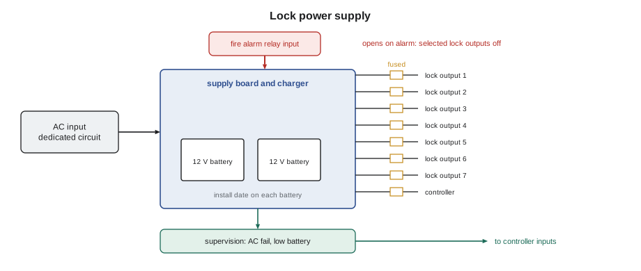
Power supplies for security and life-safety use are listed for that purpose, with features ordinary supplies lack: battery charging, supervision outputs that report AC failure and low battery to the panel or controller, separately fused or current-limited outputs, and, for lock supplies, a fire alarm input that cuts lock power when the fire alarm operates. The supplies are Class 2 power-limited sources where possible, as LVT-110 explained, which keeps the field wiring in the low-voltage category. Their AC input is a permanently wired or dedicated circuit installed by an electrician, labeled at the panel, not a convenience outlet that someone might use for a vacuum cleaner.
Loading and fusing
A supply is rated for a continuous output current, and the total load must stay within it with room to spare, because the supply also has to recharge the battery after an outage. Cobalt Line's design rule, from LVT-110, is to load supplies to no more than 80 percent of rating. The load is every device the supply powers: controllers, readers, locks held energized, and sounders. Fail-safe locks draw current all the time they are locked, which is most of the day; fail-secure locks draw only while unlocked, for a few seconds at a time, plus any time a door is scheduled unlocked. The load calculation uses the worst realistic case for each.
Each output is fused or current-limited, so a short in one lock's wiring does not take down the whole supply and every door on it. Outputs are grouped so that the doors that must work together, such as both leaves of the lobby pair, share an output, and doors that should not fail together, such as the two garage exits, are on different outputs or supplies. The output assignments are recorded inside the enclosure door.
Batteries
Security supplies use sealed lead-acid batteries, usually 12 V units of 7 to 18 ampere-hours, connected in series for 24 V systems. They are maintenance-free in the sense that they need no water, but not free of care: their capacity falls with age and heat, typically lasting three to five years, and much less in a hot room. A battery's rated capacity, in ampere-hours, is measured at a slow discharge over 20 hours; at the higher currents of a security load, the battery delivers less. Each battery is labeled with its installation date, and the maintenance program replaces batteries on a schedule, not when they fail.
The charger in the supply keeps the batteries at a float voltage, about 13.6 to 13.8 V for a 12 V battery, and recharges them after an outage. Standards for listed equipment set how quickly a discharged battery must be recharged, which is one reason the supply's load must leave headroom. Batteries in series must be the same type, size and age. Lithium batteries are appearing in some equipment but must be used only where the equipment is designed and listed for them.
How long must it last?
The required standby time comes from the specification, the owner's insurer and, for certificated systems, the listing standards. For access control, UL 294 grades access control equipment by standby power level, the highest of which is four hours, and the owner's specification sets the level required; Juniper Point's specification asks for 4 hours of normal operation followed by 15 minutes of activity at the end, which is when doors are used heavily as people respond to an outage. For intrusion systems, monitored commercial systems commonly need a full day of standby with enough left to sound the alarm; the Juniper Point locker panel's specification asks for 24 hours standby and 15 minutes of alarm.
The standby calculation is simple arithmetic, repeated carefully. Add the current every device draws in the standby state, multiply by the standby hours; add the current in the alarm or active state, multiply by the active time; add the two to get ampere-hours; then divide by a derating that allows for the battery's age and temperature. Cobalt Line uses a factor of 1.25, the LVT-110 design rule. Choose the next battery size up.
# Battery size for the Juniper Point P1 access control supply (12 V)
standby_loads = {  # device: (count, amps each in normal operation)
    "two-door controller": (3, 0.25),
    "reader (OSDP)": (6, 0.12),
    "fail-safe maglock, lobby pair": (2, 0.50),
    "fail-secure strike, idle": (3, 0.0),
    "door position and exit sensors": (6, 0.03),
}
active_extra = {  # extra amps during the activity period at the end
    "strikes released often": (3, 0.45 * 0.3),    # each strike energized about 30 % of the time
    "readers beeping and lit": (6, 0.05),
}
standby_h, active_h, derate = 4, 0.25, 1.25
i_sb = sum(n * a for n, a in standby_loads.values())
i_act = i_sb + sum(n * a for n, a in active_extra.values())
ah = (i_sb * standby_h + i_act * active_h) * derate
print(f"standby current {i_sb:.2f} A for {standby_h} h, active current {i_act:.2f} A for {active_h * 60:.0f} min")
print(f"required capacity with derating: {ah:.1f} Ah")
for size in (7, 12, 18, 26, 40):
    if size >= ah:
        print(f"choose {size} Ah at 12 V (two in parallel if the enclosure holds only smaller units)")
        break
supply_rating = 6.0
print(f"supply load {i_act:.2f} A of {supply_rating} A ({100 * i_act / supply_rating:.0f} %, limit 80 %)")standby current 2.65 A for 4 h, active current 3.35 A for 15 min required capacity with derating: 14.3 Ah choose 18 Ah at 12 V (two in parallel if the enclosure holds only smaller units) supply load 3.35 A of 6.0 A (56 %, limit 80 %)
The calculation gives about 14 ampere-hours, so an 18 Ah battery, which fits the enclosure. The 6 A supply is loaded to just over half its rating, leaving room for recharging. The two maglocks are most of the standby load; that is typical, because fail-safe locks draw current around the clock.
# Intrusion panel battery: 24 h standby plus 15 minutes of alarm
panel_sb, panel_alarm = 0.18, 0.25       # amps for the panel board
devices_sb = 0.025 * 10 + 0.035 * 2      # 10 dual-tech detectors, 2 keypads
communicator = 0.09                      # dual-path communicator, average
siren = 0.0 if False else 0.8         # silent alarm in this partition: no siren load
i_sb = panel_sb + devices_sb + communicator
i_al = panel_alarm + devices_sb + communicator + siren
ah = (i_sb * 24 + i_al * 0.25) * 1.25
print(f"standby {i_sb:.3f} A x 24 h, alarm {i_al:.3f} A x 15 min")
print(f"required: {ah:.1f} Ah -> {'18' if ah <= 18 else '26'} Ah battery")standby 0.590 A x 24 h, alarm 1.460 A x 15 min required: 18.2 Ah -> 26 Ah battery
The intrusion panel's long standby time makes even a small current add up: a little over half an ampere for a day needs more than 14 ampere-hours before derating and a 26 Ah battery after it, which is why low-current detectors and communicators matter on panels with long standby requirements.
Power over Ethernet for security devices
Edge controllers and IP cameras powered by PoE take their backup from the switch's uninterruptible power supply, the UPS. That moves the battery calculation from the door to the telecommunications room: the UPS must carry the switch and every PoE device for the required time. A PoE-powered edge controller that also powers its lock from PoE must stay within its port's power budget, and the lock's current, especially a maglock's continuous current, uses a large part of a PoE+ port. Where the lock needs more, or where the controller's PoE cannot meet the lock's inrush, a local lock supply is used, with its own battery and fire alarm input.
# Can a PoE+ edge controller power its own lock?
PORT_W = {"PoE (Class 3)": 12.95, "PoE+ (Class 4)": 25.5, "PoE Class 6": 51.0}   # watts at the device
controller_w = 4.0                    # controller and reader
for lock, volts, amps in [("12 V strike, fail-secure", 12.0, 0.45),
                          ("12 V maglock, fail-safe", 12.0, 0.50),
                          ("24 V exit device, inrush", 24.0, 1.6)]:
    need = controller_w + volts * amps / 0.85     # lock converter about 85 % efficient
    fits = [name for name, w in PORT_W.items() if w >= need]
print(f"{lock:26s} needs {need:5.1f} W -> {fits[0] if fits else 'local lock supply'}")12 V strike, fail-secure needs 10.4 W -> PoE (Class 3) 12 V maglock, fail-safe needs 11.1 W -> PoE (Class 3) 24 V exit device, inrush needs 49.2 W -> PoE Class 6
The strike and the maglock fit within even a standard PoE port, but the exit device's inrush needs nearly 50 W, far more than PoE+ can supply; only a Class 6 port would carry it. The P1 stair door is on a panel-based controller anyway, so it has its own local supply, which is the supply whose fire alarm input was missing in lesson 7.
The fire alarm interface
Lock power supplies have a fire alarm input, usually a pair of terminals that must see a closed contact for the outputs to stay on. The fire alarm contractor provides a relay that opens on alarm, through an interface module listed for the fire alarm system. When the relay opens, the supply cuts power to the outputs selected for release, which unlocks fail-safe locks and releases maglocks. The supply's selection of which outputs follow the fire alarm is set with jumpers or switches, and must match the door release design: fail-secure doors that protect valuables are often not released, while every door in an exit path is. The fire alarm input is tested as part of the fire alarm system's verification, with the fire alarm contractor and often the fire inspector present.
Testing on battery
Every supply is tested by removing its mains power and watching what happens. The AC failure supervision output should report to the panel or controller, and the event should reach the monitoring station or the access system log. The doors and devices should keep working on battery. Battery voltage under load is measured and recorded. For a full discharge test, done at acceptance on certificated systems and periodically after, the system runs on battery for its required time and then performs its alarm or activity load, proving the batteries and the calculation. After any test, the supply must recharge the batteries within the time its listing requires, and the installer checks the charging voltage.
# Record of a battery test on the P1 supply
readings = [  # minutes after AC removed, battery volts under load
    (0, 13.2), (30, 12.7), (60, 12.6), (120, 12.5), (180, 12.4), (240, 12.2), (255, 12.0)]
cutoff = 10.5        # supply's low-battery disconnect
low_batt = 11.5      # low-battery supervision threshold
print("minute  volts  status")
for m, v in readings:
    status = "low battery" if v < low_batt else "normal"
    print(f"{m:6d}  {v:5.1f}  {status}")
final = readings[-1][1]
print(f"after 4 h 15 min the battery is at {final} V, {final - cutoff:.1f} V above the cutoff: test passed")minute volts status
0 13.2 normal
30 12.7 normal
60 12.6 normal
120 12.5 normal
180 12.4 normal
240 12.2 normal
255 12.0 normal
after 4 h 15 min the battery is at 12.0 V, 1.5 V above the cutoff: test passedWorked problem
Doors that lock in a power cut
During a storm, Juniper Point loses mains power for three hours. The next morning residents report that the gym and pool doors stopped reading cards after about an hour, although the specification asks for four hours. What should Maya check?
Show solution
- Those doors are on the amenity-floor controllers, not the P1 controllers, so check that supply's batteries.
- The amenity supply's batteries are labeled as installed when the building opened, more than five years ago.
- Testing them shows a fraction of their rated capacity; aged batteries cannot carry the load for four hours.
- She replaces them with new batteries sized by the calculation, labels them with the date, runs a discharge test, and recommends the owner add battery replacement to the maintenance schedule.
Answer: The new batteries carry the amenity doors for more than four hours in the test. The owner adds a four-year battery replacement cycle for every supply.
Common mistakes
MistakeFeeding a security supply from a convenience outlet.
InsteadUse a dedicated, labeled circuit installed by an electrician.
MistakeLoading a supply to its full rating.
InsteadKeep load under 80 percent so batteries can recharge.
MistakeForgetting that fail-safe locks draw current all day.
InsteadInclude their continuous current in standby.
MistakeSizing batteries without derating.
InsteadApply the age and temperature factor and pick the next size up.
MistakeLeaving batteries until they fail.
InsteadDate-label them and replace on a schedule.
Summary and key terms
- Panels, access supplies, PoE switches and local lock supplies are separate power sources, each with backup.
- Listed security supplies have charging, supervision outputs, fused outputs and a fire alarm input.
- Load supplies to no more than 80 percent; fuse outputs so one fault does not take down every door.
- Sealed lead-acid batteries last about three to five years; label and replace them on schedule.
- Battery capacity equals standby current times hours plus active current times time, divided by derating.
- PoE edge controllers can power small locks; larger locks need a local supply.
- Every supply is tested on battery, and the fire alarm input with the fire alarm contractor.
- Standby time
- How long a system must run on battery after mains power fails.
- Derating factor
- An allowance for battery aging and temperature in the capacity calculation.
- Float voltage
- The voltage a charger holds a fully charged battery at.
- Supervision output
- A supply output that reports AC failure or low battery.
- Fire alarm input
- A supply input that cuts lock power when the fire alarm operates.
- UPS
- Uninterruptible power supply, the battery backup for network equipment.
- Discharge test
- A test that runs a system on battery for its required time.
Practice problems
Work each problem on paper first, then reveal the answer to check.
A system draws 0.5 A for 4 h and 0.8 A for 15 min. With a 1.25 factor, what capacity is needed?
Show answer
About 2.75 Ah.
Why do fail-safe locks dominate standby load?
Show answer
They draw current whenever they are locked.
What should happen when the fire alarm relay opens?
Show answer
The supply cuts power to the outputs selected for release.
How often should sealed lead-acid batteries be replaced?
Show answer
On a schedule, typically every three to five years.
Lesson quiz · 5 questions
Score 60% or more to complete this lesson.
Create a free account to save your progress, take quizzes and earn a certificate.