
ENGG-160 · Lesson 3 of 5 · 36 min
Engineering drawings
An engineering drawing is a legal and technical instruction. A fabricator in another city, who has never spoken to you, must be able to make exactly the part you intend from the drawing alone, and if something goes wrong, the drawing is what lawyers and inspectors will read. Words describe ideas; drawings describe geometry precisely enough to build.
Most drawings today are produced in CAD (computer-aided design) software, and buildings and infrastructure are increasingly modeled in BIM (building information modeling). But the conventions underneath have not changed: projection, line types, dimensions, tolerances and title blocks. This chapter teaches you to read and produce drawings that follow them, using a handrail bracket and the plan of our accessible entrance as examples.
Kinds of drawing
Different jobs need different drawings.
- Sketches: freehand, quick, for thinking and discussing. Every engineer should be able to sketch a clear isometric view in a minute.
- Detail (part) drawings: one part, fully dimensioned and toleranced, with material and finish. The fabricator works from these.
- Assembly drawings: how parts fit together, with a parts list (bill of materials) and balloons identifying each part.
- Plans, elevations and sections: the language of civil and building work. A plan looks down; an elevation looks horizontally at a face; a section shows a cut.
- Schematics and diagrams: electrical circuits, piping and instrumentation diagrams (P&IDs) and flow sheets, where connections matter more than physical shape.
Orthographic projection
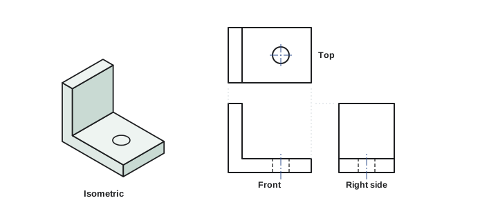
A three-dimensional object is shown on flat paper by projecting it onto planes at right angles to each other. Each projection, called a view, shows the object as seen looking straight at one face, with no perspective. Usually three views (front, top and right side) are enough; simple parts may need only two, and complex ones more.
The front view is chosen to show the most characteristic shape of the part, with the fewest hidden lines. The other views are then placed in fixed positions relative to it, and features line up between views: the width in the front view matches the width in the top view, and the height in the front view matches the height in the side view.
First-angle and third-angle
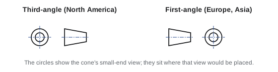
There are two conventions for arranging the views, and confusing them produces mirror-image parts.
- Third-angle projection, standard in North America: each view is placed on the same side as the face it shows. The top view goes above the front view, the right side view to the right.
- First-angle projection, standard in Europe and much of Asia: each view is placed on the opposite side. The top view goes below the front view, the right side view to the left.
Every drawing states which it uses, with a small symbol in the title block showing a truncated cone. Check it whenever you receive a drawing from overseas.
Line types
Lines carry meaning through their weight and pattern, standardized in ISO 128 and ASME Y14.2.
- Visible (object) lines: thick, continuous; edges you can see.
- Hidden lines: medium, short dashes; edges behind a surface.
- Center lines: thin, long-short chain; axes of holes and symmetry.
- Dimension and extension lines: thin, continuous, with arrowheads on dimension lines.
- Section (cutting-plane) lines: thick chain with arrows showing the viewing direction; the cut surface is hatched with thin parallel lines.
Section views
When the inside of a part matters, a section view shows it as though the part were cut along a plane and the front piece removed. The cut faces are cross-hatched. Sections replace confusing hidden lines with clear solid ones. A full section cuts all the way through; a half section cuts a symmetric part to its center line, showing inside and outside in one view. In building drawings, a wall section through the entrance would show the slab, insulation, drainage and handrail post connection in a way no plan can.
Pictorial views: isometric
Pictorial drawings show three faces at once and are easy for non-specialists to understand. The most common is isometric: the three axes are drawn 120° apart, usually with one vertical and the other two at 30° to the horizontal. All three axes are foreshortened equally.
In a true isometric projection, lengths along each axis appear at \(\sqrt{2/3} = 0.816\) of their real size. In practice, engineers usually make an isometric drawing at full length along the axes, which is simply 22% larger and much easier to measure. Lines that are not parallel to an axis (such as diagonals) are not true length in either version and must be located by plotting their end points.
Worked problem
Isometric scale
A 100 mm edge lies along an isometric axis. How long does it appear in (a) a true isometric projection, (b) an isometric drawing?
Show solution
- (a) \(100 \times 0.816 = 81.6\) mm.
- (b) 100 mm, measured directly along the axis.
Answer: 81.6 mm and 100 mm. Isometric drawings are the usual choice for sketches and assembly illustrations
Circles become ellipses in isometric. A quick freehand method: draw the isometric square (a rhombus) that would enclose the circle, then sketch the ellipse tangent to the midpoint of each side.
Scale
Most objects do not fit on paper at full size. A drawing scale states the ratio of drawn size to real size. Metric drawings use preferred scales such as 1:1, 1:2, 1:5, 1:10, 1:20, 1:50 and 1:100. American building drawings usually use architectural scales, such as 1/4 in = 1 ft-0 in (1:48) and 1/8 in = 1 ft-0 in (1:96), and site and civil drawings use engineering scales such as 1 in = 20 ft (1:240). Machine parts are often drawn full size (1:1) or larger.
Worked problem
Reading and choosing a scale
(a) On a plan of the entrance at 1/4 in = 1 ft-0 in, the ramp measures 6 in. How long is it? (b) The full 40 ft regraded walkway must fit on an 11 × 17 in sheet with about 15 in of usable width. Which architectural scale should be used, 1/2 in = 1 ft-0 in or 1/4 in = 1 ft-0 in?
Show solution
- (a) At 1/4 in per foot, each drawn inch is 4 ft: \(6 \times 4 = 24\) ft.
- (b) At 1/2 in per foot, 40 ft becomes 20 in, too wide. At 1/4 in per foot, it becomes 10 in, which fits with room for dimensions and notes.
Answer: (a) 24 ft; (b) 1/4 in = 1 ft-0 in
Never scale dimensions off a printed drawing to build from. Printers and PDF viewers resize sheets, and drawings carry the note "Do not scale" for that reason. Dimensions are written on the drawing; if one is missing, ask for it.
Dimensioning
Dimensions define size and location. A well-dimensioned drawing gives every dimension needed to make and inspect the part, once, in the view where the feature is clearest.
- Dimension each feature once. Duplicate dimensions can conflict, and the conflict will be discovered by the fabricator.
- Dimension to features that matter for function: hole centers from the surface that locates the part, not from an arbitrary edge.
- Place dimensions outside the views where possible, with extension lines leaving a small gap from the object.
- Show diameters with Ø and radii with R. On metric drawings, dimensions are in millimeters and units are omitted. Many American drawings use decimal inches instead (ASME Y14.5 covers both); the title block states which, and on inch drawings the number of decimal places often implies the tolerance.
- Avoid dimensioning to hidden lines.
Chain versus baseline dimensioning
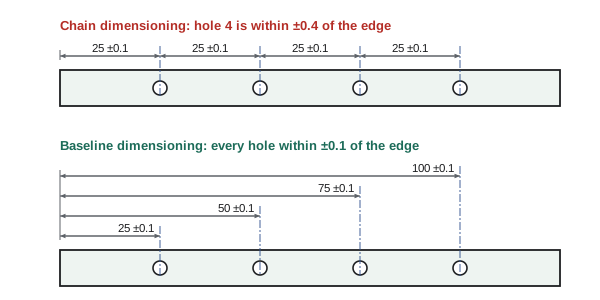
How dimensions are arranged affects accuracy. Chain dimensioning gives each feature relative to the previous one; baseline dimensioning gives every feature relative to one datum surface. Because each dimension carries a tolerance, chains accumulate error.
Worked problem
Accumulating tolerances
A bar has holes at 25 mm spacing. In the chain version, the first hole is 25 ± 0.1 from the left edge and each following hole is 25 ± 0.1 from the one before. What is the possible error in the position of the fourth hole from the edge? How does baseline dimensioning compare?
Show solution
- Chain: the fourth hole's position is the sum of four dimensions, each ±0.1: worst case \(\pm 0.4\) mm. (The spacing between the first and fourth holes, three dimensions, is ±0.3.)
- Baseline: the fourth hole is dimensioned directly as 100 ± 0.1 from the edge.
Answer: Chain: ±0.4 mm from the edge. Baseline: ±0.1 mm. Use baseline (or datum-based) dimensioning when positions relative to a reference surface matter, and chain only when the spacing between neighbors is what matters
Tolerances
No part is made exactly to size. A tolerance states how much variation is acceptable. Tighter tolerances cost more, often a lot more, so the designer's job is to make tolerances as loose as function allows.
- Limit dimensions: 25.00 / 24.95 (the largest and smallest allowed).
- Bilateral tolerance: 50 ± 0.1 (variation both ways).
- Unilateral tolerance: 50 +0.2 / 0 (variation one way only).
- General tolerances: a title block note such as "unless otherwise stated, ±0.5" covers all dimensions without their own tolerance.
Fits
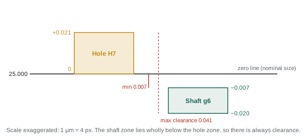
When a shaft goes into a hole, the tolerances on both decide whether the fit is a clearance fit (always a gap; the parts slide or rotate), an interference fit (always overlap; the parts are pressed together and stay put), or a transition fit (could be either). The ISO system (ISO 286) names tolerance zones with a letter for position and a number for grade: capital letters for holes, small letters for shafts. Most designs use the hole-basis system, where the hole is H (its lower limit is the nominal size) and the shaft tolerance is chosen to give the desired fit.
Worked problem
A sliding fit
A pin on the handrail bracket is specified as 25 H7/g6. For 25 mm, H7 is +0.021/0 and g6 is −0.007/−0.020. Find the limits of hole and shaft and the range of clearance.
Show solution
- Hole: 25.000 to 25.021 mm. Shaft: 24.980 to 24.993 mm.
- Minimum clearance = smallest hole − largest shaft: \(25.000 - 24.993 = 0.007\) mm.
- Maximum clearance = largest hole − smallest shaft: \(25.021 - 24.980 = 0.041\) mm.
Answer: Clearance between 0.007 and 0.041 mm: a close sliding fit, suitable for a pin that must turn freely without rattling
Tolerance stack-up
When several parts add up to a gap, their tolerances add up too. A worst-case analysis assumes every part is at its worst limit simultaneously. A statistical analysis (root sum square, RSS) recognizes that this is very unlikely when parts vary randomly, and combines tolerances as the square root of the sum of squares.
Worked problem
Stack-up in a housing
Three spacers, 20 ± 0.10, 30 ± 0.15 and 15 ± 0.05 mm, fit inside a housing 65.5 ± 0.10 mm long. Find the nominal gap and its range by worst-case and RSS methods.
Show solution
- Nominal gap: \(65.5 - (20 + 30 + 15) = 0.5\) mm.
- Worst case: tolerances add directly: \(0.10 + 0.15 + 0.05 + 0.10 = 0.40\). Gap 0.10 to 0.90 mm.
- \[\text{RSS: } \sqrt{0.10^2 + 0.15^2 + 0.05^2 + 0.10^2} = \sqrt{0.045} = 0.21 \text{ mm}\]
- Gap by RSS: 0.29 to 0.71 mm.
Answer: Nominal 0.5 mm; worst case 0.10 to 0.90 mm; RSS 0.29 to 0.71 mm. Worst case guarantees assembly; RSS is common in high-volume production, accepting a very small chance of a misfit
Geometric dimensioning and tolerancing
Size tolerances alone cannot control shape. A hole can be the right diameter but in the wrong place, or a surface the right height but warped. Geometric dimensioning and tolerancing (GD&T), defined in ASME Y14.5 (2018 edition) and the ISO GPS standards, adds controls for form (flatness, straightness), orientation (perpendicularity, parallelism), location (position) and runout, all measured from datums: reference features that mimic how the part is held and located in use. GD&T is a course of its own; for now, recognize the boxed feature control frames on drawings and know that they define exactly how each feature will be inspected.
The title block and revisions
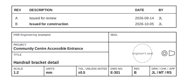
Every sheet carries a title block, normally in the bottom right corner, containing: the drawing title and number, the project, the scale, the projection symbol, units, general tolerances, material and finish (for parts), the sheet number, the names or initials of who drew, checked and approved it, and the engineer's seal where required.
Drawings change, and everyone must know which version is current. The revision block records each change with a letter or number, a description and a date. A drawing marked "Issued for construction" is authorized for building; earlier issues ("for review", "for bid") are not. In the United States, drawings submitted for permits and public works are sealed by the PE in responsible charge, as covered in ENGG-100. Working from an outdated revision is a classic and expensive site error.
CAD, BIM and the drawing of the future
CAD software generates views from a 3D model automatically, so the views always agree with each other, a big improvement on hand drafting. BIM goes further for buildings: the model carries information about every element (material, fire rating, supplier, maintenance schedule) and is shared among architects, engineers, contractors and owners. Some industries are moving toward model-based definition, where the annotated 3D model, not a 2D drawing, is the legal definition of a part. Whatever the medium, the same conventions of projection, dimensioning and tolerancing make the information unambiguous.
Common mistakes
MistakeMixing up first- and third-angle projection.
InsteadCheck the projection symbol. In third-angle, the top view sits above the front view.
MistakeDimensioning the same feature twice, or leaving one out.
InsteadEvery feature dimensioned once, in its clearest view; check that the part could be made from the dimensions given.
MistakeScaling dimensions off a print.
InsteadUse only the written dimensions; ask for any that are missing.
MistakeSpecifying tight tolerances everywhere "to be safe".
InsteadMake tolerances as loose as function allows; tight tolerances raise cost sharply.
MistakeChain-dimensioning features whose position from a datum matters.
InsteadUse baseline or datum dimensioning so tolerances do not accumulate.
MistakeBuilding from a drawing without checking its revision and status.
InsteadConfirm it is the latest revision and marked issued for construction.
Summary and key terms
- Drawings are precise technical and legal instructions; detail, assembly, plan and schematic drawings serve different purposes.
- Orthographic projection shows true-shape views at right angles; North America uses third-angle (top view above front), Europe first-angle.
- Line types carry meaning: visible, hidden, center, dimension and section lines; section views reveal interiors.
- Isometric views show three faces with axes 120° apart; true isometric foreshortens to 0.816, but drawings usually use full length.
- Use preferred scales, and never scale a print. Dimension each feature once, from functional datums.
- Tolerances define acceptable variation; fits (clearance, transition, interference) follow ISO 286; stack-ups are checked worst-case or by RSS.
- GD&T controls form, orientation and location from datums. Title blocks and revision blocks identify the drawing and its current, authorized version.
- Orthographic projection
- Views projected at right angles onto perpendicular planes.
- Third-angle projection
- View arrangement with each view on the same side as the face it shows.
- Hidden line
- A dashed line representing an edge behind a surface.
- Section view
- A view of a part as if cut by a plane, with cut faces hatched.
- Isometric
- A pictorial view with three axes drawn 120° apart.
- Scale
- The ratio of drawn size to real size.
- Tolerance
- The permitted variation in a dimension.
- Fit
- The relationship between mating parts: clearance, transition or interference.
- Datum
- A reference feature from which dimensions and tolerances are measured.
- Tolerance stack-up
- The combined effect of several tolerances on an assembly dimension.
- GD&T
- Geometric dimensioning and tolerancing, controlling form, orientation and location.
- Title block
- The area of a drawing listing its identity, scale, units, approvals and revision.
Practice problems
Work each problem on paper first, then reveal the answer to check.
On a 1:100 site plan, a path measures 63 mm. How long is it?
Show answer
63 × 100 = 6300 mm = 6.3 m.
A part 180 mm long must fit in a 90 mm space on the sheet. Which preferred scale?
Show answer
1:2 gives exactly 90 mm with no room for dimensions; use the next smaller scale, 1:5 (36 mm), or a larger sheet at 1:2.
In third-angle projection, where is the left side view placed?
Show answer
To the left of the front view.
Sketch (in words) the front, top and right side views of a 40 × 40 × 20 mm block with a 10 mm deep, 20 mm wide slot across the full top surface, running front to back.
Show answer
Front: 40 wide × 20 high rectangle with a 20 × 10 notch centered at the top. Top: 40 × 40 square with two lines 20 mm apart running front to back (the slot edges). Right side: 40 × 20 rectangle with a hidden horizontal line 10 mm below the top (the slot floor).
A dimension is 80 +0.0/−0.1. What are its limits, and is the tolerance unilateral or bilateral?
Show answer
79.9 to 80.0 mm; unilateral.
A hole is 40.000–40.025 and a shaft 40.043–40.059. What kind of fit is this, and what are its limits?
Show answer
Shaft always larger: interference fit. Minimum interference 40.043 − 40.025 = 0.018 mm; maximum 40.059 − 40.000 = 0.059 mm.
Five plates each 6.0 ± 0.1 mm thick are stacked. Find the stack thickness range by worst case and by RSS.
Show answer
Nominal 30.0. Worst case ±0.5: 29.5–30.5. RSS ±√5 × 0.1 = ±0.22: 29.78–30.22.
Six holes are chain-dimensioned at 30 ± 0.05 mm spacing starting 30 ± 0.05 from an edge. What is the worst-case positional error of the sixth hole from the edge?
Show answer
Six dimensions in the chain: ±0.30 mm.
Why might a designer accept RSS rather than worst-case stack-up?
Show answer
In high-volume production with random variation, all parts are very rarely at their limits together. RSS allows looser (cheaper) part tolerances with a small, acceptable risk of misfit. Worst case is used when every assembly must fit, such as low volumes or safety-critical parts.
List five items found in a title block.
Show answer
Any five of: title, drawing number, revision, scale, projection symbol, units, general tolerances, material, finish, sheet number, drawn/checked/approved, date, company, project, seal.
Lesson quiz · 5 questions
Score 60% or more to complete this lesson.
Create a free account to save your progress, take quizzes and earn a certificate.