
ENGG-130 · Lesson 3 of 5 · 46 min
Moments and couples
A force does two things to a body: it tends to move it along, and it tends to turn it. So far we have only dealt with the first, because all the forces passed through one point. Real structures are loaded at many different points, and the turning effect, called the moment, is often what governs the design. A cantilever balcony fails by rotating off its support, a crane tips over its outriggers, a bolt is tightened by a twisting moment, and a beam bends because of the moments along it.
This chapter defines the moment of a force in two and three dimensions, introduces Varignon's theorem and the cross product, finds moments about an axis, and then treats couples: pairs of forces that produce pure turning. It finishes with equivalent systems, the tool that lets you replace a messy set of loads with a single force and couple. Those ideas are what make rigid-body equilibrium, in the next lesson, possible.
The moment of a force
The moment of a force about a point O measures its tendency to rotate a body about that point. Its magnitude is the force times the perpendicular distance from O to the force's line of action:
The distance \(d\), called the moment arm, must be perpendicular to the line of action. Moments are measured in N·m or kN·m. In two dimensions the moment has a sense, counterclockwise or clockwise, and we usually take counterclockwise as positive. In vector terms the moment points perpendicular to the plane by the right-hand rule: curl the fingers of your right hand in the direction of rotation and your thumb gives the direction of the moment vector. Counterclockwise in the x-y plane is +z.
Two consequences follow straight from \(M = Fd\). A force whose line of action passes through O has no moment about O, however large it is. And a force can slide along its line of action without changing its moment, because the perpendicular distance does not change. That is the principle of transmissibility from Lesson 1 again.
Worked problem
Tightening a bolt
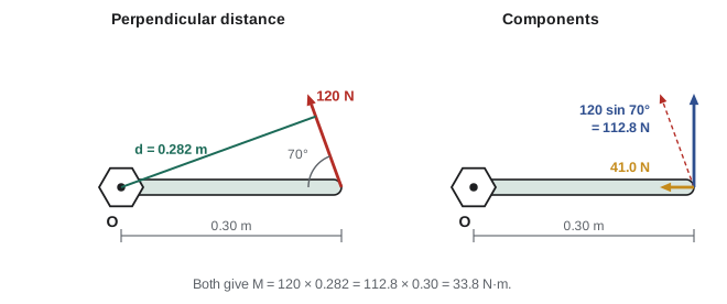
A mechanic pulls on the end of a 0.30 m wrench with 120 N. Find the moment about the bolt when the force is (a) perpendicular to the handle, (b) at 70° to the handle.
Show solution
- (a) The arm is the full handle: \(M = 120 \times 0.30 = 36.0\) N·m.
- (b) Perpendicular distance from the bolt to the line of action: \(d = 0.30\sin 70^\circ = 0.2819\) m. \(M = 120 \times 0.2819 = 33.8\) N·m.
- Equivalently, the component of force perpendicular to the handle is \(120\sin 70^\circ = 112.8\) N, acting at 0.30 m. The component along the handle passes through the bolt and contributes nothing.
Answer: (a) 36.0 N·m; (b) 33.8 N·m. Pulling at a moderate angle loses little; pulling along the handle would give no moment at all
Varignon's theorem
Finding the perpendicular distance can take awkward geometry. Varignon's theorem offers a shortcut: the moment of a force about a point equals the sum of the moments of its components about that point. Split the force into x and y components at any point on its line of action, and add their moments.
If the force acts at a point \((x, y)\) relative to O, the x-component has moment arm \(y\) and the y-component has moment arm \(x\). With counterclockwise positive:
This formula handles signs automatically, provided you use signed coordinates and signed components. It is the 2D version of the cross product you will meet shortly.
Worked problem
Moment on a bracket
A 600 N force acts at point A on a bracket, 0.50 m to the right of and 0.25 m above the support O. It points down and to the right at 40° below horizontal. Find its moment about O and the perpendicular distance from O to its line of action.
Show solution
- Components: \(F_x = 600\cos 40^\circ = 459.6\) N, \(F_y = -600\sin 40^\circ = -385.7\) N.
- \[M_O = xF_y - yF_x = (0.50)(-385.7) - (0.25)(459.6) = -192.8 - 114.9 = -307.7 \text{ N·m}\]
- Negative means clockwise. Both components turn the bracket clockwise about O: the downward part pushes the right end down, and the rightward part, acting above O, also turns it clockwise.
- Perpendicular distance: \(d = |M_O|/F = 307.7/600 = 0.513\) m.
Answer: M_O = 308 N·m clockwise, with a moment arm of 0.513 m
Moments in practice: tipping and stability
Many design checks compare two moments about the same point: one that tends to overturn a body and one that resists. Mobile cranes, retaining walls, signs in wind, and loaded shelving are all checked this way. The body tips about its edge when the overturning moment exceeds the restoring moment from its own weight.
Worked problem
Will the crane tip?
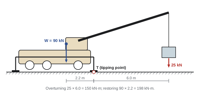
A mobile crane weighs 90 kN, and its center of gravity is 2.2 m behind its front outrigger. It lifts a 25 kN load at a horizontal distance of 6.0 m in front of that outrigger. Find the overturning and restoring moments about the outrigger, the ratio between them, and the load that would just tip the crane.
Show solution
- If the crane tips, it rotates about the front outrigger, T. Take moments there.
- Overturning: \(25 \times 6.0 = 150\) kN·m.
- Restoring: \(90 \times 2.2 = 198\) kN·m.
- Ratio: \(198/150 = 1.32\).
- Tipping load at this radius: \(198/6.0 = 33.0\) kN.
Answer: The crane is stable, with a restoring-to-overturning ratio of 1.32. It would tip at 33.0 kN. Crane load charts rate the safe load at only a fraction of the tipping load, so the rated load here would be lower still
Notice how the safe load depends on the radius. Doubling the outreach to 12 m halves the tipping load. Crane load charts reflect exactly this, which is why booming out with a suspended load is one of the most common causes of crane overturns.
Moments in three dimensions: the cross product
In 3D the perpendicular distance is hard to see, and the moment has a direction that matters. The general definition uses the vector cross product. If \(\mathbf{r}\) is a position vector from O to any point on the line of action of \(\mathbf{F}\), then
Expanding the determinant:
The magnitude is \(rF\sin\theta\), which is \(F\) times the perpendicular distance, so it agrees with \(M = Fd\). The direction is perpendicular to both \(\mathbf{r}\) and \(\mathbf{F}\), by the right-hand rule. Order matters: \(\mathbf{r}\times\mathbf{F} = -\mathbf{F}\times\mathbf{r}\). Always put \(\mathbf{r}\) first. In 2D, with \(r_z = F_z = 0\), only the k-component survives, and it is exactly \(xF_y - yF_x\).
Worked problem
Moment of a guy-cable force about the mast base
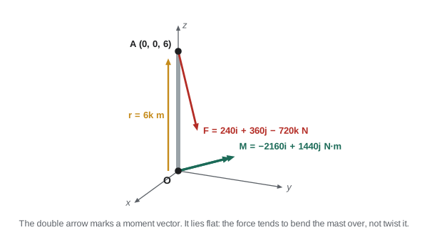
In Lesson 1, cable AB pulled the top of a 6 m mast with \(\mathbf{F} = 240\mathbf{i} + 360\mathbf{j} - 720\mathbf{k}\) N, acting at A(0, 0, 6) m. Find the moment of this force about the base O.
Show solution
- \(\mathbf{r}_{OA} = 6\mathbf{k}\) m.
- i: \(r_yF_z - r_zF_y = 0 - 6(360) = -2160\).
- j: \(-(r_xF_z - r_zF_x) = -(0 - 6 \times 240) = 1440\).
- k: \(r_xF_y - r_yF_x = 0\).
- \[\mathbf{M}_O = -2160\mathbf{i} + 1440\mathbf{j} \text{ N·m}, \qquad |\mathbf{M}_O| = 2596 \text{ N·m}\]
Answer: M_O = −2160i + 1440j N·m (2.60 kN·m). The moment is horizontal: it tries to bend the mast over, not twist it. The k-component is zero because the force passes through the mast's own axis
Moment about an axis
Often you need the turning effect about a particular line, not a point: a door about its hinges, a shaft about its bearings, a hatch about its hinge line. The moment about an axis \(a\) through O, with unit vector \(\mathbf{u}_a\), is the component of \(\mathbf{M}_O\) along that axis:
This is called the scalar triple product. A force parallel to an axis, or one whose line of action crosses it, has no moment about it. You cannot open a door by pushing toward the hinges or by pulling straight up.
Worked problem
Opening a hatch
A floor hatch is hinged along the x-axis. A rope attached at B(0.9, 0.8, 0) m pulls with 150 N toward C(0.3, 0.2, 0.3) m. Find the moment about the hinge line.
Show solution
- \(\mathbf{r}_{BC} = (-0.6, -0.6, 0.3)\) m, length 0.9 m, so \(\mathbf{F} = 150(-0.6, -0.6, 0.3)/0.9 = (-100, -100, 50)\) N.
- \(\mathbf{r}_{OB} = (0.9, 0.8, 0)\) m. Only the x-component of \(\mathbf{r}\times\mathbf{F}\) is needed: \(r_yF_z - r_zF_y = 0.8(50) - 0 = 40\) N·m.
Answer: 40 N·m about the hinge. Only the 50 N vertical part of the pull, acting 0.8 m from the hinge, helps open the hatch. The other components either cross the hinge axis or run parallel to it
Couples
A couple is two forces of equal size, opposite direction and parallel lines of action, separated by a distance \(d\). The forces cancel, so a couple produces no net force, only turning. Its moment is
and remarkably, it is the same about every point. To see why, take moments about any point O at distance \(a\) from one force: \(F(a + d) - Fa = Fd\). The \(a\) drops out. So a couple moment is a free vector: it can be moved anywhere on the body without changing its effect on the body as a whole.
Couples are everywhere. Two hands on a steering wheel, the twist applied by a tap wrench, the torque from an electric motor on its shaft, and the end moment that a welded connection delivers to a beam are all couples. Different force pairs give the same couple if \(Fd\) is the same: 100 N on a 0.4 m wheel equals 200 N on a 0.2 m wheel.
Worked problem
Steering wheel
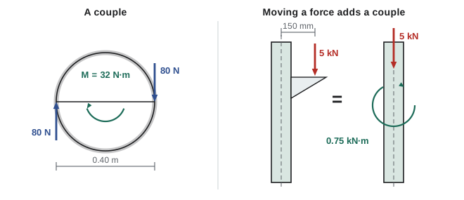
A driver pushes up with 80 N on one side of a 0.40 m diameter steering wheel and pulls down with 80 N on the other. What couple moment is applied? What force would give the same moment on a 0.36 m wheel?
Show solution
- \(M = 80 \times 0.40 = 32.0\) N·m.
- On a 0.36 m wheel: \(F = 32.0/0.36 = 88.9\) N on each side.
Answer: 32.0 N·m; 88.9 N per hand on the smaller wheel
Worked problem
Adding couples
A plate is acted on by three couples: 40 N·m counterclockwise, a pair of 150 N forces 0.20 m apart turning clockwise, and a pair of 60 N forces 0.50 m apart turning counterclockwise. Find the resultant couple.
Show solution
- Second couple: \(-150 \times 0.20 = -30\) N·m. Third: \(+60 \times 0.50 = +30\) N·m.
- Sum: \(40 - 30 + 30 = 40\) N·m.
Answer: 40 N·m counterclockwise. Because couples are free vectors, where they act on the plate does not matter
Equivalent systems
Two force systems are equivalent if they have the same resultant force and the same resultant moment about any point. Equivalent systems have the same effect on a rigid body's equilibrium (though not on its internal stresses). This lets you replace a complicated set of loads with something simpler.
Moving a force
A force can be moved to a parallel line of action through another point, provided you add a couple equal to the moment of the force about the new point. Physically: add equal and opposite forces at the new point. One of them, with the original force, forms a couple; the other is the moved force.
Worked problem
Eccentric load on a column
A 5.0 kN beam reaction sits on a bracket 150 mm from the centreline of a steel column. Replace it with an equivalent force and couple at the column centreline.
Show solution
- The force moves to the centreline unchanged: 5.0 kN downward.
- Add a couple equal to its moment about the centreline: \(5.0 \times 0.150 = 0.75\) kN·m, turning in the same sense as the original offset load.
Answer: 5.0 kN down at the centreline plus a 0.75 kN·m couple. The column must be designed for both: the couple bends it, which an axial load alone would not
That is why structural engineers care so much about eccentricity. A column designed only for the axial load would be unsafe if the load is applied off-center, because the hidden couple adds bending stress.
Reducing a system to a single resultant
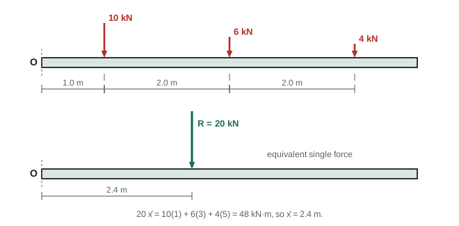
Any system of forces in a plane can be reduced to a single force \(\mathbf{R} = \sum\mathbf{F}\) acting at O plus a couple \(M_{RO} = \sum M_O\). If \(\mathbf{R}\) is not zero, you can go one step further and shift \(\mathbf{R}\) sideways until its own moment equals \(M_{RO}\). The result is a single force with no couple, located at perpendicular distance \(d = M_{RO}/R\) from O.
Worked problem
Resultant of loads on a beam
A beam carries downward loads of 10 kN at 1.0 m, 6 kN at 3.0 m and 4 kN at 5.0 m from its left end O. Find the single equivalent force and its location.
Show solution
- \(R = 10 + 6 + 4 = 20\) kN downward.
- Moments about O (clockwise, taking each load times its distance): \(10(1.0) + 6(3.0) + 4(5.0) = 48\) kN·m.
- Location: \(20\,\bar{x} = 48\), so \(\bar{x} = 2.4\) m.
Answer: 20 kN downward at 2.4 m from O
The same idea gives the resultant of a distributed load. A uniform load \(w\) (in kN/m) over a length \(L\) is equivalent to a single force \(wL\) at the middle of the loaded length. A triangular load is equivalent to its area, \(\tfrac{1}{2}wL\), at the centroid of the triangle, one third of the way from its tall end. You will use both constantly in the next lesson.
Common mistakes
MistakeUsing the distance to the point where the force is applied rather than the perpendicular distance to its line of action.
InsteadThe moment arm is perpendicular to the line of action. If that is awkward, use components and Varignon's theorem instead.
MistakeMixing sign conventions within one equation.
InsteadState the convention (counterclockwise positive is standard) and decide each term's sense from the sketch.
MistakeWriting F × r instead of r × F.
InsteadOrder matters; F × r gives the moment in the opposite direction. Position vector first.
MistakeTaking r from the force's point of application to O.
Insteadr runs from the moment center O to any point on the line of action.
MistakeTreating a couple as if its moment depends on the point chosen.
InsteadA couple has the same moment about every point. It can be moved freely on a rigid body.
MistakeMoving a force to a new point without adding the couple.
InsteadA moved force needs a couple equal to its moment about the new point to stay equivalent.
Summary and key terms
- The moment of a force about a point is M = Fd, with d perpendicular to the line of action. Counterclockwise is usually positive.
- Varignon's theorem: the moment of a force equals the sum of the moments of its components; in 2D, M_O = xF_y − yF_x.
- Stability checks compare overturning and restoring moments about the tipping edge.
- In 3D, M_O = r × F, with r from O to any point on the line of action.
- The moment about an axis is M_a = u_a · (r × F). Forces parallel to or crossing the axis contribute nothing.
- A couple is two equal, opposite, parallel forces. Its moment Fd is the same about every point.
- A force can be moved to a new point by adding a couple. Any planar system reduces to a single resultant force located at d = M/R.
- Moment
- The turning effect of a force about a point or axis, in N·m.
- Moment arm
- The perpendicular distance from the moment center to the line of action.
- Varignon's theorem
- The moment of a force equals the sum of the moments of its components.
- Right-hand rule
- Curl the fingers in the direction of rotation; the thumb points along the moment vector.
- Cross product
- r × F, a vector perpendicular to both with magnitude rF sin θ.
- Scalar triple product
- u · (r × F), the moment of a force about an axis.
- Couple
- Two equal, opposite, non-collinear parallel forces producing pure rotation.
- Free vector
- A vector, such as a couple moment, that can act anywhere on a body.
- Equivalent system
- A set of forces and couples with the same resultant force and moment as another.
- Eccentricity
- The offset of a load from the axis of the member that carries it.
Practice problems
Work each problem on paper first, then reveal the answer to check.
A 250 N force acts horizontally at the top of a 1.8 m post. Find its moment about the base.
Show answer
M = 250 × 1.8 = 450 N·m.
A 40 N force acts at (0.3, 0.2) m, with components (−24, 32) N. Find its moment about the origin.
Show answer
M = xFy − yFx = 0.3(32) − 0.2(−24) = 9.6 + 4.8 = 14.4 N·m counterclockwise.
A 1.2 m pole is hinged at its base and tilted 30° from vertical. A horizontal rope at its top pulls with 200 N. What moment does the rope create about the base?
Show answer
The perpendicular distance to a horizontal force is the vertical height: 1.2 cos 30° = 1.039 m. M = 207.8 N·m.
A sign 2.0 m wide and 1.5 m tall, weighing 3.0 kN, is mounted on a 3.0 m post. Wind of 2.4 kN acts at the sign's center, 3.75 m above the base. The footing's own weight is 12 kN and its edge is 0.9 m from the center. Is it stable against tipping?
Show answer
Overturning: 2.4 × 3.75 = 9.0 kN·m. Restoring: (12 + 3.0) × 0.9 = 13.5 kN·m. The ratio is 1.5, so it is stable.
Find r × F for r = (2, 0, 1) m and F = (0, 300, 0) N.
Show answer
i: 0·0 − 1·300 = −300; j: −(2·0 − 1·0) = 0; k: 2·300 − 0 = 600. M = −300i + 600k N·m.
For the mast example, find the moment about O of the AC cable force, (−420, 210, −420) N at A(0, 0, 6).
Show answer
i: 0 − 6(210) = −1260; j: −(0 − 6(−420)) = −2520; k: 0. M = −1260i − 2520j N·m.
A force F = (50, 0, 120) N acts at (0, 0.6, 0) m. Find its moment about the z-axis.
Show answer
Mz = xFy − yFx = 0 − 0.6(50) = −30 N·m.
Two 400 N forces form a couple with a moment of 120 N·m. How far apart are they?
Show answer
d = 120/400 = 0.30 m.
Replace a 12 kN horizontal force acting 0.8 m above point O with an equivalent system at O.
Show answer
12 kN horizontal at O plus a 9.6 kN·m couple, in the sense the original force turned the body about O.
Loads of 8 kN at 0.5 m, 12 kN at 2.0 m and 5 kN at 4.5 m act downward on a beam. Find the resultant and its location from the left end.
Show answer
R = 25 kN. Moment = 4 + 24 + 22.5 = 50.5 kN·m. x̄ = 2.02 m.
Lesson quiz · 5 questions
Score 60% or more to complete this lesson.
Create a free account to save your progress, take quizzes and earn a certificate.