
ELV-230 · Lesson 10 of 12 · 21 min
Brakes and brake adjustment
Ray said he trusted only two things on an elevator completely, and he tested both of them whenever he could: the safeties, which ELV-320 will cover, and the brake. On a traction car the brake does two jobs. Every time the car stops at a floor, the drive brings it to rest electrically and the brake sets to hold it there, so the brake is a holding brake thousands of times a day. And when anything goes wrong while the car is moving, the safety circuit opens, the drive and the brake lose power together, and the brake must stop the moving car by itself, so it is also an emergency brake. This lesson covers how elevator brakes work, what the codes require of them, how they are adjusted and tested, and the newer devices that protect against an empty car rising too fast or a car moving away from a floor with its doors open.
How an elevator brake works
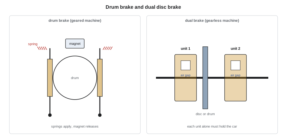
Elevator machine brakes are spring-applied and electrically released. Springs press friction linings against a drum or disc on the machine shaft; an electromagnet, when energized, pulls the linings away against the springs. If power is lost for any reason, whether a safety circuit opens, a fuse blows or the building loses power, the springs set the brake. That fail-safe principle is the basis of every elevator brake: the brake never needs power to stop the car, only to release it.
- Drum brakes. Two shoes with linings, on arms pivoted to the machine frame, close on a drum on the motor or sheave shaft. A compression spring on each arm, or a single spring between the arms, applies the force, and a magnet with one or two plungers pushes the arms open. Tillicum car 1's 1962 machine has a drum brake on the coupling between motor and worm, with one magnet and two shoes acting together.
- Disc and caliper brakes. Brake units with spring-applied armature plates or calipers act on a disc on the shaft. Most permanent-magnet gearless machines, including Quayside's, have two independent brake units acting on the sheave shaft or a drum cast with the sheave.
- Brake monitoring. Modern brakes have switches or sensors that tell the controller whether each brake unit has lifted and set. The controller checks each unit on every run and prevents the next run if a unit fails to lift or set, because a brake that is dragging overheats and a brake that does not set cannot hold the car.
What the codes require of a brake
The codes require the driving-machine brake of a passenger elevator to be able to stop the car from rated speed and hold it with 125 percent of the rated load in the car, and to hold the empty car against the counterweight. The extra 25 percent covers overloading and gives a margin for testing. The brake must apply automatically when power is removed, and the stopping must not be so violent that it injures passengers or so slow that the car overshoots dangerously. On a geared machine with the brake on the motor side of the gear, the brake works through the gear; on a gearless machine, it acts directly on the sheave.
The newer codes added two protections that older single brakes cannot give. Ascending car overspeed protection must stop an empty or lightly loaded car that is rising too fast, as it might if the brake failed and the counterweight, heavier than the car, pulled it up. Unintended movement protection must stop a car that moves away from a landing with its doors open, for example because of a brake or drive failure, before it moves far enough to trap or shear a person in the doorway. Both need an emergency brake that is independent of the faults it protects against. The devices used include a second independent brake on a gearless sheave, a rope gripper that clamps the ropes, a brake acting on the rails or a safety gear that works upward. Cars built before these rules, like Tillicum car 1, do not have them, and many jurisdictions require them to be added when the machine, brake or controller is altered; some have set dates by which older cars with single brakes must be upgraded. Tillicum car 2 gained both protections with its new dual-brake machine last term.
Brake torque and stopping distance
The torque a brake must produce follows from the unbalance it must hold and the deceleration it must give. To hold a car at rest with 125 percent load, the brake torque at the sheave must at least equal the unbalance torque. To stop a moving car, it must also supply the torque to decelerate everything that moves: the car, its load, the counterweight, the ropes and the rotating parts of the machine.
The stopping distance is the distance traveled while the brake sets, at almost full speed, plus the braking distance at the deceleration the brake gives.
# Quayside car 2 brake: torque to hold 125 % load and to stop it going down, and the stopping distance
g = 1
car, rated, cwt = 3300, 3500, 4875        # lb
d, r = 16 / 12, 2                                   # sheave pitch diameter (ft), roping
unbalance = car + 1.25 * rated - cwt            # car side heavier with 125 % load
t_hold = unbalance * g * d / (2 * r)
moving = car + 1.25 * rated + cwt               # moving mass, ignoring ropes and rotating parts
a = 3.3                                          # deceleration, ft/s2
t_stop = (unbalance * g + moving * a / 32.2) * d / (2 * r)
print(f"hold 125 % load: {t_hold:,.0f} lb-ft at the sheave; stop it going down at {a} ft/s2: {t_stop:,.0f} lb-ft")
v = 500 / 60                                          # rated speed, ft/s
for t_react in (0.10, 0.25):
    s = v * t_react + v ** 2 / (2 * a)
print(f"brake reaction {t_react:.2f} s: stopping distance about {s:.1f} ft")hold 125 % load: 933 lb-ft at the sheave; stop it going down at 3.3 ft/s2: 1,362 lb-ft brake reaction 0.10 s: stopping distance about 11.4 ft brake reaction 0.25 s: stopping distance about 12.6 ft
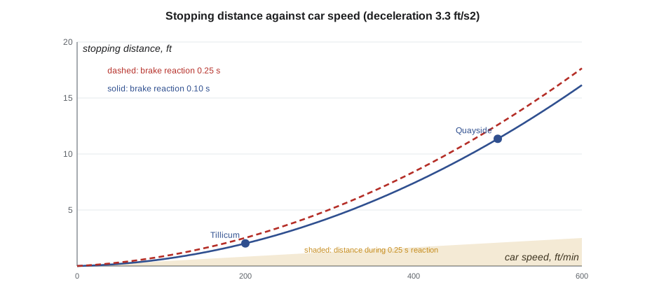
The stop torque is roughly half again the holding torque at this deceleration, and the reaction time adds noticeably to the stopping distance at Quayside's speed. A brake that sets slowly, because its magnet's stored energy is released slowly or its plunger sticks, lets the car run on before braking starts. That is why brake setting time is measured on new installations and after brake work, and why the brake circuits on modern controllers include a fast discharge path for the magnet coil, as ELV-210 described.
On Tillicum's geared machine, the brake is on the motor side of the worm, so it needs only a small fraction of the sheave torque: the sheave torque divided by the gear ratio. When the car side is heavier and running down, the gear is being driven from the sheave side, and the gear's backdriving losses help the brake. A brake on the motor side depends on the gear, the worm shaft, the coupling and the gear's keys to transmit its torque to the sheave, which is one reason the newer codes require protection that does not depend on those parts.
Adjusting a drum brake
Brake adjustment follows the maker's instructions for the machine, and on an old machine without instructions, Northcrest's own procedure written from the machine's design. Ray did Tillicum car 1's brake adjustment with Tamsin during the annual examination, with the car empty at the top landing, the counterweight landed on a support or with the car on its stops as the procedure required, and the machine locked out except when they ran it for tests.
- Inspect first. Check the drum for scoring, glazing, oil and cracks, the linings for wear and contamination, the pins and bushings of the arms for wear, the springs for cracks and corrosion, and the magnet and its plunger for free movement. A brake contaminated with oil, for example from a leaking worm shaft seal, must be cleaned and its linings replaced and the leak repaired; it cannot be adjusted to work.
- Set the shoe clearance. With the brake lifted, the gap between each lining and the drum is set to the specified value, small and equal all round, so that both shoes clear the drum without dragging and set quickly. Unequal clearance makes one shoe do most of the work and wear fast.
- Set the spring. The spring's compressed length sets the braking force, and so the brake torque. It is set to the length on the machine's brake data, or adjusted until the brake meets its test, and locked with its lock nuts. A spring set too long gives too little torque; set too short, the brake grabs and may not lift fully on low voltage.
- Set the magnet stroke. The plunger's travel is set so the brake lifts fully at the minimum operating voltage and sets quickly, with the specified gap at the magnet when the brake is lifted.
- Test. Run the car and check the brake lifts cleanly, the car stops smoothly, and the brake sets and holds. Then do the brake tests the program requires, below. Record the clearances, spring lengths, magnet stroke and test results.
# Tillicum car 1 brake adjustment record: compare the readings with the brake data
data = {"shoe clearance": (0.008, 0.016), "spring length": (3.78, 3.86), "magnet stroke": (0.12, 0.20)}   # in, low and high
readings = {
    "left shoe clearance": ("shoe clearance", 0.010),
    "right shoe clearance": ("shoe clearance", 0.022),
    "left spring length": ("spring length", 3.82),
    "right spring length": ("spring length", 3.84),
    "magnet stroke": ("magnet stroke", 0.16),
}
for name, (key, value) in readings.items():
    lo, hi = data[key]
    print(f"{name:<22} {value:6.3f} in  range {lo:.3f} to {hi:.3f}  {'ok' if lo <= value <= hi else 'ADJUST'}")
left, right = readings["left shoe clearance"][1], readings["right shoe clearance"][1]
if abs(left - right) > 0.004:
print("shoe clearances unequal: one shoe is doing most of the work")left shoe clearance 0.010 in range 0.008 to 0.016 ok right shoe clearance 0.022 in range 0.008 to 0.016 ADJUST left spring length 3.820 in range 3.780 to 3.860 ok right spring length 3.840 in range 3.780 to 3.860 ok magnet stroke 0.160 in range 0.120 to 0.200 ok shoe clearances unequal: one shoe is doing most of the work
The right shoe's clearance was over the range and well above the left's, so the left shoe had been doing most of the braking. They reset both shoes to the middle of the range, rechecked the springs and stroke, and the brake then set evenly and quietly.
Testing brakes
Brake tests prove that the brake can do what the code requires, and they are done at acceptance, after any brake or machine work, and periodically as the maintenance part of the code and the program require. The full test, with 125 percent of rated load in the car, is done with test weights and is part of the periodic full-load tests; Lesson 12 includes one at Tillicum. Between those, simpler tests check the brake's condition.
- Holding test. With the car at a floor and the drive holding it at zero speed, or with test loads, the brake is set and the drive's torque removed; the car must not move. Modern drives can do a brake torque test by applying a set torque against the closed brake and measuring any movement of the sheave.
- Stopping test. The car is stopped from speed by opening the safety circuit, and the stopping distance or deceleration is measured and compared with previous results. Changes show lining wear, contamination or a spring change.
- Individual unit test. On a dual brake, each unit is tested alone, with the other held open as the maker's procedure describes, to prove that each can hold the car by itself.
- Monitoring test. Each brake switch or sensor is checked to prove that the controller detects a brake unit that fails to lift or to set.
Worked problem
Stopping distance at Tillicum
Tillicum car 1 runs at 200 ft/min. In a stopping test, the brake sets in 0.20 s and decelerates the car at 4.0 ft/s². What is the stopping distance?
Show solution
- Distance during reaction 3.33 × 0.20 = 0.67 ft (200 ft/min = 3.33 ft/s).
- Braking distance 3.33² / (2 × 4.0) = 1.39 ft.
- Total 2.06 ft.
Answer: About 2.1 ft, to be compared with the car's previous test results.
Common mistakes
MistakeAdjusting an oily brake.
InsteadClean, replace contaminated linings and fix the leak; adjustment cannot cure contamination.
MistakeSetting one shoe tight and the other loose.
InsteadSet equal clearances so both shoes share the work.
MistakeShortening the spring to stop a slide.
InsteadFind why the brake slides; an over-compressed spring may stop the brake lifting at low voltage.
MistakeTesting only both brake units together.
InsteadProve each unit of a dual brake can hold the car alone.
MistakeAssuming an old single brake meets today's code.
InsteadOlder cars lack ascending car overspeed and unintended movement protection; alterations may require them.
Summary and key terms
- Elevator brakes are spring-applied and electrically released, so loss of power sets them.
- The brake must stop and hold 125 percent of rated load and hold the empty car against the counterweight.
- Newer codes require protection against ascending car overspeed and unintended movement, usually by an independent emergency brake.
- Brake torque comes from the unbalance and the deceleration; stopping distance adds reaction distance to braking distance.
- Adjustment covers inspection, shoe clearance, spring length and magnet stroke, recorded each time.
- Brakes are tested for holding, stopping, each unit alone and monitoring.
- Spring-applied brake
- A brake set by springs and released by an electromagnet, so it sets on loss of power.
- Driving-machine brake
- The brake on the machine that holds the car at floors and stops it in an emergency.
- Emergency brake
- An independent brake that stops the car for ascending car overspeed or unintended movement.
- Ascending car overspeed
- An empty or light car rising too fast, pulled by the heavier counterweight.
- Unintended movement
- Car movement away from a landing with the doors open, not commanded by the controls.
- Shoe clearance
- The gap between brake lining and drum with the brake lifted.
- Rope gripper
- A device that clamps the suspension ropes to stop the car in an emergency.
Practice problems
Work each problem on paper first, then reveal the answer to check.
Why are elevator brakes spring-applied?
Show answer
So that loss of power for any reason sets the brake.
A gearless 2:1 car has an unbalance of 2,200 lb and a sheave of 16 in. What holding torque is needed at the sheave?
Show answer
2,200 × 16 / 12 / 4 = 733 lb-ft.
What is the stopping distance from 400 ft/min with a 0.15 s reaction and 3.3 ft/s² deceleration?
Show answer
1.0 + 6.7 = 7.7 ft (400 ft/min = 6.67 ft/s).
Why must each unit of a dual brake be tested alone?
Show answer
Each must be able to hold the car by itself if the other fails.
What is ascending car overspeed protection for?
Show answer
To stop an empty or light car rising too fast if the brake or machine fails.
Lesson quiz · 5 questions
Score 60% or more to complete this lesson.
Create a free account to save your progress, take quizzes and earn a certificate.