
ELV-220 · Lesson 6 of 12 · 20 min
Jacks, cylinders and plungers
The drilling rig came into Holloway through the loading dock on a Saturday night, folded down to fit under the corridor ceiling, and was walked into car 2's hoistway on its tracks with plywood under them to protect the floors. It drilled a new hole beside the old one, about 43 ft deep and wide enough for a steel casing. Over the following week the old jack was cut up and pulled out in sections, the new cylinder, sealed inside a plastic liner, was lowered into the new hole, and the hole around it was filled. Tamsin worked on all of it, and by the end of the week she knew more about the jack, the part of a hydraulic elevator nobody sees, than most mechanics learn in years.
The parts of a jack
A hydraulic jack has two main parts: the cylinder, which holds the oil, and the plunger, which slides out of it and carries the car. On a direct-acting elevator, the cylinder is a heavy steel pipe, closed at the bottom and fitted at the top with a head that guides the plunger and seals around it.
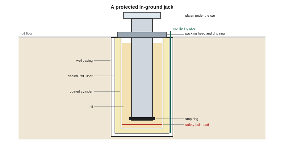
- The cylinder is made from heavy-wall steel pipe with a welded bottom. Current code requires a safety bulkhead, a second bottom plate a short distance above the first with a small orifice in it, so that if the bottom fails, oil can escape only slowly through the orifice and the car descends slowly instead of falling.
- The cylinder head, or packing head, is bolted or threaded to the top of the cylinder. It holds the packing or seals that keep oil from escaping around the plunger, a wiper ring to keep dirt off the seal, and guide bearings that keep the plunger centered.
- A bleeder screw near the top of the cylinder lets air trapped at the top of the cylinder be released when the system is filled or after work.
- A drip ring or collector under the head catches the small amount of oil that seeps past the packing as the plunger moves. On many cars a small scavenger pump returns this oil to the tank.
- The plunger is a smooth, hard-surfaced steel tube or bar. Its top is fixed to the car's platen plate under the sling. A stop ring near its bottom end prevents it from leaving the cylinder if the car overtravels at the top.
- Long plungers and cylinders are made in sections joined by threaded or bolted couplings, which must be aligned carefully so the plunger runs true.
Packing and seals
The packing at the cylinder head is a wear item. Old cars used braided or rope packing compressed by a gland; most now use molded seals, often U-cups or chevrons, with a wiper. A new seal lets through only a film of oil, which lubricates the plunger and is caught by the drip ring. As the seal wears, or if the plunger is scored or corroded, the seepage grows, the scavenger pump runs more often, and oil appears on the cylinder head and pit floor. Replacing the packing means taking the weight of the car off the plunger, usually by landing the car on blocking or timbers in the pit or holding it with the rigging set up as in the rigging course, then opening the head.
The plunger surface is what the seal rides on, and it must be protected. Weld spatter, paint, a dragged tool or grit from a dusty pit scratches it, and every scratch tears the seal. Ray keeps the exposed plunger covered with a clean sleeve when work is going on above it, and he never lets anyone stand on the cylinder head.
Buried cylinders: why they fail
A buried cylinder sits in soil that may be wet, salty or electrically active, for decades. Steel corrodes in those conditions. Corrosion through the cylinder wall lets oil out into the ground, which is an environmental problem and a sign the cylinder is weakening. Corrosion around the bottom weld of a single-bottom cylinder is a safety problem: when the bottom lets go, the car drops with nothing to slow it except the friction of the plunger and the oil rushing out. Failures of this kind are the reason the code now requires safety bulkheads and corrosion protection, and why regulators have pushed owners to replace or protect single-bottom cylinders.
Stray electrical currents in the ground can speed up corrosion, a process sometimes called electrolysis. Older cylinders were often electrically connected to the building's piping and grounding, which can make them part of a path for current. Modern installations isolate the cylinder electrically from the building and use plastic liners, coatings or cathodic protection to keep the steel from corroding.
Protecting a new in-ground cylinder
The new installation at Holloway follows the protected method the code allows. In order:
- Drill the hole and set a steel well casing to hold the soil back. The casing is not part of the hydraulic system.
- Install a plastic liner, a PVC pipe with a solvent-welded bottom cap, inside the casing. The liner is sealed against groundwater and against oil.
- Test the liner for leaks before the cylinder goes in, typically by filling it with water and checking that the level holds for a set time.
- Lower the new cylinder, which has a safety bulkhead and a protective coating, into the liner and set it plumb, using the rigging and alignment fixtures specified by the manufacturer.
- Fill the space between the cylinder and liner and between liner and casing as the manufacturer specifies, commonly with sand or a non-corrosive fill, and seal the top of the liner.
- Install a monitoring pipe from the bottom of the liner to the pit, so that any oil leaking from the cylinder collects in the liner where it can be detected and pumped out, instead of escaping into the soil.
The monitoring pipe turns a hidden problem into a visible one. During periodic inspections, the mechanic checks the pipe with a dipstick or a small pump; oil in the liner means the cylinder is leaking. At Holloway, Lena added the check to the maintenance control program for both cars.
The plunger as a column
With the car at the top, a long plunger is a slender column carrying the car and its load, and like any column it can buckle if it is too slender for its load. The code gives a formula for the allowable plunger load based on the plunger's size, wall thickness, unsupported length and material, and the manufacturer designs the plunger to it. Mechanics do not design plungers, but understanding buckling explains why a plunger must be straight, why its guides must be in good condition, and why the stop ring and overtravel limits matter.
This is Euler's formula for the critical load of a column, with E the modulus of the steel, I the second moment of area of the tube, L its unsupported length and K a factor for how its ends are held. A plunger guided at the cylinder head and held by the car guides at the top behaves roughly like a column pinned at both ends, K about 1; if its top were free to move sideways, K would be about 2 and the critical load would drop to a quarter. The code's formula is more conservative than Euler's, but the shape is the same: the critical load falls with the square of the length.
# Plunger buckling check, Euler formula (illustrative only; plunger design uses the code formula)
import math
E = 29e6                      # steel modulus, psi
D, d = 6.0, 5.1            # outside and inside diameters of the plunger tube, in
L = 41.5                      # unsupported length with the car at the top, ft
I = math.pi * (D ** 4 - d ** 4) / 64
load = 11000                # car, sling, plunger and rated load, lb
for K, ends in ((1.0, "guided at both ends"), (2.0, "top free to sway")):
    pcr = math.pi ** 2 * E * I / (K * L * 12) ** 2
print(f"K = {K}: {ends:<20} critical load {pcr :,.0f} lb, ratio to working load {pcr / load:.1f}")K = 1.0: guided at both ends critical load 35,094 lb, ratio to working load 3.2 K = 2.0: top free to sway critical load 8,774 lb, ratio to working load 0.8
Guided at both ends, the plunger has a comfortable ratio of critical load to working load. With its top free to sway, the critical load falls below the working load, and the plunger would buckle. That is the reason car guide shoes and rails matter on a hydraulic car even though no safety gear runs on them: they hold the top of the plunger in line.
Installing and aligning the jack
A jack must be plumb and in line with the car guide rails, so that the plunger runs straight through its head and the car rides without side loads. Out-of-plumb jacks wear the packing and guides on one side, bind, and in extreme cases bend the plunger. During the Holloway installation, Ray checked plumb with a long level and a plumb line in two directions at right angles, both on the cylinder before it was set and on the plunger after the sections were coupled. The plunger's top connection to the platen has some freedom built in, often a bolted plate with slotted holes or a ball joint on some designs, so that a small misalignment between rails and jack does not force the plunger sideways.
Plunger sections are joined by couplings that must be tightened and locked to the manufacturer's values, and the joints must be smooth so they do not tear the packing as they pass through the head. Before the new jack was filled, Tamsin wiped every joint and Ray checked the surfaces with his fingertips for any burr.
Testing and filling a new jack
Once the jack is installed and piped to the power unit, the system is filled with oil and the air is bled out. Air collects at the top of the cylinder, under the head, and at high points in the piping. The car is run up and down at slow speed several times and the bleeder screw is opened at the top of the cylinder until clear oil, without bubbles, appears. Air left in the cylinder makes the ride spongy and can cause the car to bounce or sink as the air compresses and dissolves.
The new jack and piping are then pressure tested as the code and the manufacturer require, before the car is put in service, and the result is part of the acceptance test in Lesson 10. Lena also had the old cylinder's hole sealed and the oil-soaked soil removed from around it by an environmental contractor, with the waste manifests filed with the hospital's records.
Worked problem
Displacement and fill volume for the new jack
The new Holloway car 2 cylinder has an inside diameter of 7.5 in and a length of 42.5 ft. The plunger is 6 in in diameter. With the car at the bottom, about 41.5 ft of plunger is inside the cylinder. How much oil fills the cylinder with the car at the bottom?
Show solution
- The cylinder's inside volume is π × 7.5² / 4 × 510 = 22,530 in³, or 97.5 gal.
- The plunger inside the cylinder occupies π × 6² / 4 × 498 = 14,080 in³, or 61 gal (taking its outside volume, since it is sealed).
- The oil fills the space between: 97.5 − 61 = 36.5 gal, plus the piping.
Answer: About 37 gal of oil fills the cylinder with the car down; as the car rises, oil equal to the plunger's displacement is added from the tank.
Common mistakes
MistakeLetting tools or weld spatter mark the plunger.
InsteadCover and protect the plunger; every scratch tears the seal.
MistakeThinking a well casing protects the cylinder from corrosion.
InsteadThe casing holds back soil; the sealed liner, coating and isolation protect the cylinder.
MistakeIgnoring oil in the liner's monitoring pipe.
InsteadOil there means the cylinder is leaking; report it and plan repairs.
MistakeFilling a new jack without bleeding the air.
InsteadBleed at the cylinder head and high points until clear oil appears.
MistakeForcing the platen bolts to pull an out-of-line plunger into place.
InsteadCorrect the alignment; the plunger must run straight.
Summary and key terms
- A jack is a cylinder and plunger; the cylinder head holds the seals, wiper and guides.
- Packing seepage is normal in small amounts; the drip ring and scavenger pump return it to the tank.
- Buried cylinders corrode; single-bottom cylinders can fail suddenly, which is why safety bulkheads and protection are required.
- A protected installation uses a casing, a sealed and tested liner with a monitoring pipe, a coated cylinder with a safety bulkhead and electrical isolation.
- A long plunger is a column; its guides and straightness protect it from buckling.
- New jacks are aligned plumb, filled, bled and pressure tested before service.
- Cylinder head
- The top of the cylinder, holding the seals, wiper and plunger guides.
- Safety bulkhead
- A second bottom in the cylinder with a small orifice that limits the car's descent if the bottom fails.
- Liner
- A sealed plastic pipe around a buried cylinder that keeps leaking oil out of the soil.
- Monitoring pipe
- A pipe from the bottom of the liner to the pit, used to detect leaked oil.
- Scavenger pump
- A small pump that returns packing seepage to the tank.
- Stop ring
- A ring on the plunger that stops it leaving the cylinder.
- Bleeder
- A screw at the top of the cylinder for releasing trapped air.
Practice problems
Work each problem on paper first, then reveal the answer to check.
Why does a safety bulkhead have a small orifice?
Show answer
So that if the bottom fails, oil escapes slowly and the car descends slowly instead of dropping.
What does oil in the monitoring pipe tell the mechanic?
Show answer
The cylinder is leaking into the liner.
Why do the car's guide shoes matter to the plunger on a hydraulic car?
Show answer
They hold the top of the plunger in line, so it acts as a column guided at both ends.
By what factor does the Euler critical load change if the unsupported length doubles?
Show answer
It falls to one quarter.
Where does air collect in a newly filled jack?
Show answer
At the top of the cylinder under the head, and at high points in the piping.
Lesson quiz · 5 questions
Score 60% or more to complete this lesson.
Create a free account to save your progress, take quizzes and earn a certificate.