
ELV-220 · Lesson 4 of 12 · 21 min
Power units, pumps and motors
The new power unit for Holloway car 2 arrived on a pallet at the loading dock, a steel tank about the size of a chest freezer with a valve block on its top and a sealed cover hiding the motor and pump inside. Ray and Tamsin had moved the old unit out the week before, using the rigging plan from their rigging course, and now they moved the new one in the same way. Before they set it on its isolation pads, Priya walked Tamsin around it, pointing to each part and asking what it did. "You will spend more time at the power unit than anywhere else on a hydraulic," she said. "This is where you read the pressure, listen to the pump, adjust the valve and check the oil. Know every fitting on it."
What a power unit contains
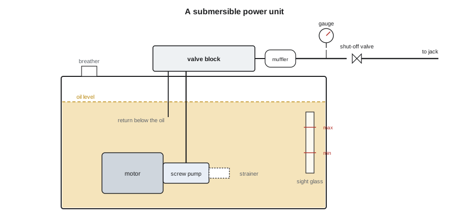
A hydraulic power unit, sometimes called a pumping unit, brings together everything that makes and controls the flow of oil. Its main parts are:
- The tank, which holds the oil that is not in the jack and piping, lets air and dirt separate from returning oil, and gives up heat through its walls. It has a fill cap with a breather, a sight glass or dipstick with level marks, and a drain.
- The pump, which takes oil from the tank and delivers it under pressure to the valve block.
- The motor, which drives the pump, mounted inside the tank on submersible units or outside on dry units.
- The control valve block, mounted on top of the tank, which sends pump flow to the jack for up travel, returns it to the tank when the car is not moving up, meters oil back from the jack for down travel and holds the car still when it is stopped. Lesson 5 covers it in detail.
- The pressure relief valve, usually built into the valve block, which limits the pressure the pump can produce.
- The manual shut-off valve on the line to the jack, required by code, which isolates the jack from the power unit for service and testing.
- The muffler or silencer, a chamber in the pressure line that damps pressure pulses from the pump, which would otherwise be heard in the car and the building.
- Accessories such as a suction strainer, return filter, oil heater, oil cooler, oil thermometer or temperature sensor, pressure gauge with an isolating valve, and the low oil or pump run timer protection.
Submersible and dry units
Most new power units are submersible: the motor and pump sit in the oil at the bottom of the tank. The oil cools the motor and quiets the pump, so these units are compact and quiet, which matters in a hospital. The motor is a special design with insulation that resists oil, and its leads leave the tank through a sealed terminal box. The disadvantage is that the motor's heat goes straight into the oil, and to service the pump or motor the mechanic must drain or pump out the tank and lift them out.
Older units, and some new ones for large or fast cars, are dry units: the motor sits on top of or beside the tank and drives the pump through a coupling or V-belts. The motor is cooled by air, and the pump may be outside the tank too, drawing oil through a suction line. Dry units are noisier, but the motor is easy to reach and its heat goes into the room rather than the oil. The Marlowe has a dry unit with a flexible coupling between motor and pump, the coupling Ray and Tamsin replaced in her first year.
Pumps
Elevator pumps are positive-displacement pumps: each revolution moves a fixed volume of oil, the displacement, from the inlet to the outlet. Three types are used.
- Screw pumps, the common choice on modern units, use a central power rotor with a helical thread meshing with two idler rotors in a close-fitting housing. Oil is carried along in the cavities between the threads in a smooth, continuous flow with little pulsation, so they are quiet.
- Gear pumps, external or internal, trap oil between gear teeth and the housing. They are simple and robust but noisier and pulse more than screw pumps.
- Vane pumps, now rare on elevators, use sliding vanes in a rotor turning in an off-center housing.
The flow a pump delivers is its displacement times its speed, less the internal leakage, or slip, back from the outlet to the inlet. Slip rises with pressure and with lower viscosity, which is why a worn pump with hot oil loses most flow when the car is loaded. The ratio of actual flow to theoretical flow is the volumetric efficiency.
Here D is the displacement per revolution, n the speed and η the volumetric efficiency, which is above 0.9 for a healthy pump at working pressure. Because the motor speed is almost fixed, an induction motor running a few percent below synchronous speed, the flow of a given pump is almost fixed too, and the car's up speed is set by the pump size. Changing the up speed of a hydraulic car means changing the pump, the motor speed or, with a variable-frequency drive on the motor, the motor frequency.
# Pump flow and volumetric efficiency from timed up runs (Holloway car 2, new pump)
import math
displacement = 10.1         # in3 per revolution, from the pump data
rpm = 3500                    # two-pole motor at 60 Hz, about 3 % slip
theory = displacement * rpm / 231          # gpm
area = math.pi * 6.0 ** 2 / 4
travel = 30.0                  # ft timed section of the run at full speed
for name, seconds in (("empty car", 17.6), ("rated load", 18.1)):
    speed = travel / seconds
    flow = area * speed * 60 * 12 / 231
    print(f"{name:<10} {travel} ft in {seconds} s: speed {speed * 60:.0f} ft/min, flow {flow:.0f} gpm, volumetric efficiency {100 * flow / theory:.0f} %")
print(f"theoretical pump flow {theory:.0f} gpm")empty car 30.0 ft in 17.6 s: speed 102 ft/min, flow 150 gpm, volumetric efficiency 98 % rated load 30.0 ft in 18.1 s: speed 99 ft/min, flow 146 gpm, volumetric efficiency 95 % theoretical pump flow 153 gpm
The new pump delivers about 98 percent of its theoretical flow empty and about 95 percent loaded, as expected. Tamsin recorded both times on the start-up sheet. If, years from now, the loaded run takes several seconds longer while the empty run is unchanged, the pump's slip has grown and it is wearing.
Motors for hydraulic power units
Power unit motors are three-phase induction motors, usually two-pole for screw pumps, running at about 3,500 rpm. They start unloaded: when the motor starts, the valve's bypass is open and the pump's flow returns to the tank at low pressure, so the motor reaches speed before the valve closes the bypass and sends flow to the jack. That makes reduced-voltage starting practical, and new units use soft starters or wye-delta starters to limit the starting current, as Lesson 8 explains.
Elevator motors work in short bursts. A hydraulic motor runs only for the up trips, perhaps 20 to 30 seconds each, and then rests. Manufacturers therefore rate them for intermittent duty, with a number of starts per hour, and a motor that would be too small for continuous running is right for elevator service. Too many starts per hour, or long runs at high pressure, overheat the windings. On a submersible motor, overheating also heats the oil. Many units have thermal sensors in the windings, connected to the controller, which stop the car at the next landing if the motor gets too hot.
The motor's nameplate current, the full-load current at rated output, is a key number. A clamp meter on one phase during a loaded up run should read close to it; much more means overload, high pressure or a supply problem, and much less with a slow car means the pump is not delivering. The motor overload protection in the starter is set from the nameplate current.
The tank and oil volume
The tank must hold enough oil to fill the jack and piping when the car is at the top, with oil still covering the pump inlet by a safe margin, and enough extra room that the oil returning from the jack when the car is at the bottom does not overflow it. The difference between the oil level with the car at the top and at the bottom is the volume displaced by the plunger: plunger area times stroke. The tank also needs a reserve below the minimum level for the pump to draw from without sucking air, and space above the maximum for foam and expansion.
# Oil volume and tank check for Holloway car 2
import math
d = 6.0 / 12                      # plunger diameter, ft
stroke = 40.5                 # plunger stroke, ft
displaced = math.pi * d ** 2 / 4 * stroke * 7.48        # gal
piping = 12              # oil in the pipe, hose and valve, gal
pump_cover = 16         # oil that must stay above the pump inlet, gal
headroom = 0.10              # ten percent space above the maximum level
need = (displaced + pump_cover) * (1 + headroom) + piping
tank = 100                # usable tank volume from the data plate, gal
print(f"oil displaced by the plunger {displaced:.0f} gal")
print(f"tank volume needed about {need:.0f} gal; tank supplied {tank} gal -> {'OK' if tank >= need else 'too small'}")
plan = 5.9                  # tank plan area, ft2
per_unit = plan * 7.48 / 12    # gal of oil per in of level
print(f"level change between car at bottom and car at top: about {displaced / per_unit:.0f} in ({per_unit:.1f} gal per in)")oil displaced by the plunger 59 gal tank volume needed about 95 gal; tank supplied 100 gal -> OK level change between car at bottom and car at top: about 16 in (3.7 gal per in)
The level marks on the sight glass reflect this. The oil should be checked with the car at the bottom landing, where the tank level is highest, and compared with the mark for that position; checked with the car at the top, the level is lower and normal. Ray taught Tamsin to always note the car's position when she records the oil level, because a level that looks low with the car at the top may be fine, and one that looks normal with the car at the top would overflow the tank when the car comes down.
Low oil protection
If a jack or pipe leaks, the tank gradually loses oil. Eventually the pump cannot deliver enough to reach the top floor and keeps running as the car crawls or stops short. The code requires protection against this. The usual method is a pump run timer: the controller times each up run, and if the motor runs longer than the normal run time plus a margin without the car reaching its destination, it stops the pump, lowers the car to the bottom landing, opens the doors and removes the car from service until a mechanic resets it. Some units use a low-level float switch instead. A car that keeps tripping its low oil protection is losing oil, and the leak must be found, which is the subject of Lesson 11.
Noise and vibration
A hospital or apartment building notices noise from the power unit. Pump pulsation, the motor's hum and the oil rushing through the valve can travel through the pipe and building structure into the car and nearby rooms. New units are mounted on rubber isolation pads, connected to rigid piping through a short flexible hose or an isolating coupling, and fitted with a muffler. Pipe clamps along the run to the jack have rubber inserts. At Holloway, the hospital's specification limited the noise in the corridor outside the machine room, so the contractor added acoustic lining to the machine room door and Lena had a sound reading taken at commissioning.
Worked problem
Choosing between a worn pump and a slipping valve
Dunmore Square's car runs up at rated speed empty but slows by about 20 percent with a full load. The motor current loaded is close to nameplate. The oil is at 110 °F. Is the problem the pump or a valve?
Show solution
- Normal current with full load means the pressure is about right, so the car is not overloaded and there is no blockage.
- Lost speed under load means flow is going somewhere other than the jack. It could be pump slip, which rises with pressure, or a valve leaking flow back to the tank, such as a bypass not closing fully.
- The oil is in range, so heat is not the cause.
- Test the valve by closing the manual shut-off valve and running the pump against it: the relief valve should open at its set pressure. If the gauge rises to that pressure promptly and holds, the bypass and other valve paths are sealing. A slow rise, or a pressure that cannot reach the setting, points to the pump.
- Confirm with the pump manufacturer's flow-pressure data if needed, before ordering a pump.
Answer: The shut-off valve test separates pump slip from valve leakage; the result decides whether the repair is a pump or a valve adjustment.
Common mistakes
MistakeChecking the oil level without noting where the car is.
InsteadThe level depends on car position; check with the car at the bottom landing against the correct mark.
MistakeRunning a submersible motor out of oil on the bench.
InsteadIt is cooled by the oil and can overheat in seconds without it.
MistakeAssuming a higher motor current means a better pump.
InsteadCurrent reflects pressure; flow is shown by car speed.
MistakeResetting a low oil trip and leaving.
InsteadRepeated trips mean oil is being lost; find the leak.
MistakeConnecting a new power unit with rigid pipe straight to the building.
InsteadIsolation pads, a flexible connection and a muffler keep noise out of the building.
Summary and key terms
- The power unit holds the tank, pump, motor, valve block, relief valve, shut-off valve, muffler and accessories.
- Submersible units are compact and quiet; dry units keep the motor in air and are easier to service.
- Positive-displacement pumps deliver displacement times speed, less slip that rises with pressure and heat.
- Up speed is set by the pump flow; timed runs empty and loaded reveal pump wear.
- Motors are rated for intermittent duty, start unloaded and are protected against overheating and overload.
- The tank must cover the plunger displacement, a pump reserve and headroom; low oil protection stops a car that is losing oil.
- Power unit
- The assembly of tank, pump, motor and valves that supplies and controls the oil.
- Submersible unit
- A power unit whose motor and pump are submerged in the oil.
- Displacement
- The volume a pump moves per revolution.
- Slip
- Internal leakage in a pump from outlet back to inlet.
- Volumetric efficiency
- Actual pump flow divided by theoretical flow.
- Muffler
- A chamber that damps pressure pulses in the pressure line.
- Pump run timer
- Low oil protection that stops the pump if an up run takes too long.
Practice problems
Work each problem on paper first, then reveal the answer to check.
Why do submersible motors need special insulation?
Show answer
They run in oil, which must not attack the winding insulation.
A pump has a displacement of 6.1 in³ and turns at 3,500 rpm. What is its theoretical flow?
Show answer
6.1 × 3,500 / 231 = 92 gpm.
Why can a hydraulic pump motor use a soft starter?
Show answer
It starts unloaded with the valve bypass open.
What volume of oil does a 5 in plunger with a 30 ft stroke displace?
Show answer
π × 5² / 4 × 360 = 7,069 in³ = 30.6 gal.
What does a pump run timer do when it trips?
Show answer
It stops the pump, lowers the car to the bottom landing, opens the doors and takes the car out of service.
Lesson quiz · 5 questions
Score 60% or more to complete this lesson.
Create a free account to save your progress, take quizzes and earn a certificate.