
ELV-130 · Lesson 8 of 12 · 19 min
Hoisting and setting the machine
The machine is the heaviest single part of most traction elevators and the one that ends up in the most awkward place. On a machine-room-less elevator like the Quayside cars, it sits on a bedplate at the very top of the hoistway, just under the overhead slab, with the hoistway open below. On a machine-room elevator like the Tillicum cars, it sits on beams in a penthouse above the hoistway, reached through a trap door or a roof hatch. This lesson follows the Quayside car 2 machine lift from the plan to the last bolt, and uses it to bring together the weight, center of gravity, sling, hardware, hoist and rigging point checks of the earlier lessons. The Tillicum machine replacement, which needs a crane, is the capstone in Lesson 12.
The lift in outline
The machine for car 2 weighs 1,320 lb according to its nameplate and manual, and it is lifted bolted to its bedplate, which adds 200 lb. It arrived at the 30th floor in the construction hoist, crated, and was uncrated in the corridor and moved on a heavy-duty dolly to the car 2 entrance. From there, it has to cross the sill into the hoistway, rise from the landing level to its support about 8.5 ft above the top landing floor, and be lowered onto the bedplate seats on the rail tops. The hoist beam above, rated 4,400 lb, carries the main hoist. A rated anchor point in the corridor floor slab, installed for the purpose and marked, holds a lever hoist that controls the machine as it leaves the landing.
The work platform hung from the hoist beam during rail setting has been removed, because it would be in the way, and a rated temporary deck has been built across the hoistway at the top landing, at sill level, on beams bearing in pockets in the hoistway walls that the general contractor formed for the purpose. The deck is what the crew stands on while the machine goes up, and it closes the hoistway below the lift for the whole operation. It is designed and marked for people and light tools. The machine never rests on it.
| Item | Value | Source |
|---|---|---|
| Machine | 1,320 lb | Nameplate and manual |
| Bedplate | 200 lb | Packing list, checked against drawing |
| Rigging: bridle, shackles, hoist rings | 55 lb | Weighed at the branch |
| Main hoist: electric chain hoist | 2,000 lb rated | Hoist nameplate |
| Hoist beam | 4,400 lb rated, pulls up to 15° from vertical | Marking and engineer's letter |
| Landing anchor and lever hoist | 3,300 lb anchor, 1,500 lb lever hoist | Anchor marking, hoist nameplate |
Rigging the machine
Lesson 2 found the combined center of gravity of the machine and bedplate, toward the motor end, and Lesson 3 worked out the tensions in a two-leg bridle with the hook over the center of gravity. The manual shows two lifting lugs on the bedplate and states that the machine is to be lifted only by them, with the legs at no less than 60 degrees from horizontal. The bridle is an adjustable chain bridle with grade 100 legs, shortened on the motor side with the shortening clutch so that the master link sits above the center of gravity, and connected to the lugs through bolt-type shackles with the pins secured. Softeners are not needed at the lugs, but a pad goes over the brake housing where a leg passes close to it.
Before any lift, the rigging gets a trial. With the machine still on its dolly, the main hoist takes up the slack and lifts it a fraction of an inch. Ray watches the bedplate with a level on it. If one end rises first, the bridle is adjusted and the trial repeated. When the bedplate comes up level, the machine is lowered back onto the dolly and the hoist brake is checked by lifting again and stopping. The trial also confirms the weight: the electric hoist has a load display, and it reads within a few percent of the planned figure.
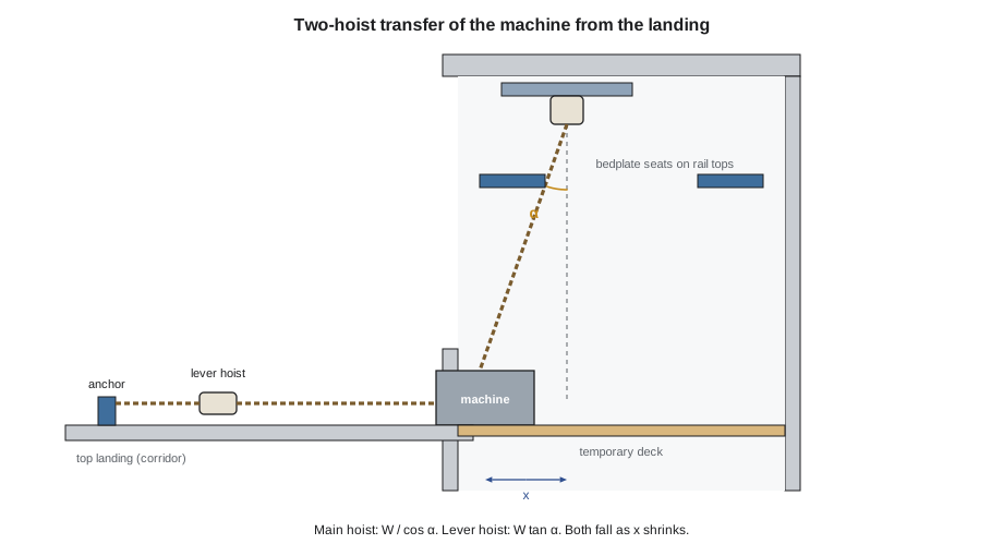
The transfer from the landing
The machine starts on its dolly at the sill, with its center of gravity about 30 in horizontally from the plumb line under the hoist beam hook, which is 11.5 ft above it. When the main hoist takes the load, its chain cannot be vertical: it leans from the hook down to the machine at an angle α from vertical. Left to itself, the machine would swing out over the hoistway as it left the dolly, toward the plumb line and beyond. The lever hoist, anchored behind it in the corridor and attached to the bedplate with a short sling, holds it back. As the main hoist lifts, the lever hoist is paid out a click at a time, and the machine moves out over the hoistway under control until it hangs plumb below the hook and the lever hoist goes slack.
The tensions in the two hoists follow from the balance of forces on the machine. With the lever hoist pulling horizontally, the main hoist's vertical component carries the weight and its horizontal component is balanced by the lever hoist.
At the start, when the angle is largest, the main hoist carries a little more than the weight, and the lever hoist carries a fraction of it. As the machine moves out toward the plumb line, the angle decreases, the main hoist tension falls toward the weight, and the lever hoist tension falls toward zero. The code below works through the transfer and checks each hoist and the hoist beam's angle limit.
# Two-hoist transfer of the machine from the landing: tensions as it moves out
import math
W = 1575                 # machine + bedplate + rigging (lb)
H = 11.5                 # hook height above the machine's lifting point (ft)
main_rated, lever_rated = 2000, 1500     # (lb)
beam_angle_limit = 15   # degrees from vertical, from the engineer's letter
for x in (2.5, 1.75, 1.0, 0.5, 0.0):         # horizontal offset from the plumb line (ft)
    a = math.atan2(x, H)
    t_main, t_lever = W / math.cos(a), W * math.tan(a)
    flags = []
    if t_main > main_rated: flags.append("main hoist over rating")
    if t_lever > lever_rated: flags.append("lever hoist over rating")
    if math.degrees(a) > beam_angle_limit: flags.append("beam angle limit exceeded")
print(f"x = {x:4} ft: angle {math.degrees(a):4.1f} deg, main {t_main:5.0f} lb, lever {t_lever:4.0f} lb {', '.join(flags) or 'ok'}")x = 2.5 ft: angle 12.3 deg, main 1612 lb, lever 342 lb ok x = 1.75 ft: angle 8.7 deg, main 1593 lb, lever 240 lb ok x = 1.0 ft: angle 5.0 deg, main 1581 lb, lever 137 lb ok x = 0.5 ft: angle 2.5 deg, main 1576 lb, lever 68 lb ok x = 0.0 ft: angle 0.0 deg, main 1575 lb, lever 0 lb ok
The angle is about 12 degrees at the start, inside the beam's 15-degree limit, and the main hoist is at its highest tension then, still well under its rating. The lever hoist never carries more than about a fifth of the weight. If the machine had started farther back from the plumb line, or the hook had been lower, the angle would have exceeded the beam's limit, and the plan would have needed a different method, such as rolling the machine farther out on a rated bridge before lifting. Ray made Tamsin run the numbers for a start 4 ft back, which gives about 19 degrees, so that she could see where the plan stops working.
During the transfer, the people are placed so that nobody is in line with the lever hoist chain, which stores energy as it stretches, and nobody is on the hoistway side of the machine. The operator of the main hoist stands on the temporary deck to one side, the lever hoist operator stands in the corridor beside the anchor, and Ray, as signal person and person in charge, stands where he can see both and the machine. The controlled zone is the hoistway below the deck, which is closed, and the corridor in line with the lever hoist.
Lifting to the support
Once the machine hangs plumb, the lever hoist is disconnected and the machine is raised slowly to its support height. The tag line, held by the deck operator, keeps it from turning so that the motor end stays toward the counterweight side, as the layout shows. As it rises, the crew checks the clearances to the rails, the rail brackets and the overhead, which on this layout are tight: the sheave guard clears the overhead slab by about 4 in in the final position. The machine is raised a little above its seats, and the bedplate is turned into its final orientation with the tag line.
Landing the machine is done in stages. The machine is lowered until the bedplate is just above the seats on the rail tops, the locating holes are lined up with drift pins pushed through by hand, and only then is the machine lowered onto the seats. The hoist is not slackened until the bedplate is fully seated and its bolts are started. Fingers stay out of the gap between the bedplate and the seats at all times; alignment is done with the drift pins and a bar, never by hand.
Setting and aligning
When the machine is seated, the rigging stays attached with the hoist just slack until the bolts are tightened, so that the machine can be lifted again if something is wrong. The setting checks from ELV-120 then follow: position of the drive sheave relative to the rail lines and the rope drop points, level of the bedplate, plumb of the sheave, vibration isolation pads seated and not bridged, bolts torqued and marked, and seismic restraints fitted. Shims, where needed, are full-size steel shims under the bearing points, and the machine is lifted the small amount needed to place them, never pried up with a bar while someone's hand is under it.
Only when the machine is bolted down, checked and accepted by the mechanic in charge is the rigging removed, and the shackles, bridle and hoist are inspected again before they are packed away. A protective cover goes over the machine until the hoistway work above it is finished.
Machine room lifts
On a machine-room elevator, the machine lift has a different shape. The machine goes into the machine room through a trap door in the floor, a door from the roof, or a hatch, and is moved across the room on a trolley beam or on rollers to its position over the rope holes. The machine room hoist beam, if there is one, usually runs above the machine position and the trap door, with a trolley so that a hoist can lift from the trap door and travel to the machine. The rules are the same, with two differences. The machine room floor carries the load during the move, so its capacity and the load path to the beams below have to be known. And the old machine, on a modernization, must be removed first, which means its ropes are taken off, the car and counterweight are secured, and the old machine's weight is confirmed before it is lifted, as Tamsin's estimate in Lesson 2 prepared for.
Securing the car and counterweight before the ropes come off is a rigging task in its own right. The car is landed on its safeties at the bottom of the hoistway or supported on blocking, the counterweight is landed on its buffer or blocking, and both are confirmed to be resting fully on their supports before any rope is cut or unshackled. A rope taken off a car that is still hanging on it lets the car drop onto its safeties at best, and at worst drops the counterweight. Lessons 9 and 10 cover car and counterweight supports in detail.
Checking the plan against the lift
After the lift, Tamsin compared the plan with what happened. The weight read by the hoist matched the plan within three percent. The bridle adjustment from the trial lift was a single link. The transfer took longer than planned because the lever hoist was paid out more slowly than expected, which Ray said was the right way round. The tag line was needed more than expected because the machine wanted to turn as it rose, which she added to her notes for the next three cars. And the clearance to the overhead was as tight as the layout said, which was a reminder that the layout dimensions had been checked in the survey, not assumed.
Ray's comment on the lift was short. Nothing about it was difficult once the numbers were known, and every number was known before the machine left the dolly. That, he said, is what a good lift looks like from the outside: boring.
Common mistakes
MistakeLifting the machine from a motor eyebolt or by a choker around the housing.
InsteadLift only from the lifting points the manual specifies.
MistakeLetting the machine swing off the landing into the hoistway on the main hoist alone.
InsteadHold it back with a second hoist and pay it out under control.
MistakeIgnoring the hoist beam's angle limit during the transfer.
InsteadCalculate the angle at the start position and change the method if it exceeds the limit.
MistakeGuiding the bedplate onto its seats with fingers.
InsteadUse drift pins and a bar, with hands clear of the gap.
MistakeRemoving the rigging before the bolts are tight.
InsteadKeep the hoist attached and just slack until the machine is fastened and checked.
Summary and key terms
- The machine lift brings together weight, center of gravity, slings, hardware, hoists and rigging points.
- A trial lift confirms balance, weight and the hoist brake before the real lift.
- In a two-hoist transfer, the main hoist carries W / cos α and the lever hoist W tan α.
- The start position and hook height decide the angle, which must stay within the beam's rating.
- The machine is landed in stages with drift pins, and the rigging stays on until it is fastened.
- Machine room lifts add floor capacity and the safe removal of the old machine with the car and counterweight supported.
- Two-hoist transfer
- A method in which one hoist lifts and a second holds the load back, moving it from a landing to a plumb position.
- Plumb line (of a hook)
- The vertical line directly below a hoist hook.
- Drift pin
- A tapered pin used to line up bolt holes before the bolts are fitted.
- Bedplate
- The steel base on which a machine is mounted and through which it is fastened to its support.
- Trap door
- A floor opening in a machine room through which equipment is lifted in and out.
- Temporary deck
- A rated platform built across a hoistway to provide a working surface and close the hoistway below.
Practice problems
Work each problem on paper first, then reveal the answer to check.
A 1,500 lb machine hangs from a hoist whose chain is 10 degrees from vertical, held back by a horizontal lever hoist. What does each hoist carry?
Show answer
Main: 1,500 / cos 10° = 1,523 lb; lever: 1,500 × tan 10° = 264 lb.
The hook is 10 ft above the load and the load starts 2.5 ft from the plumb line. What is the starting angle?
Show answer
atan(2.5 / 10) = 14 degrees.
Why does the rigging stay attached after the machine is seated?
Show answer
So it can be lifted again if something is wrong before it is fastened and checked.
What must be done before the ropes are removed from an old machine?
Show answer
Land the car and counterweight on their safeties, buffers or blocking and confirm they are fully supported.
Lesson quiz · 5 questions
Score 60% or more to complete this lesson.
Create a free account to save your progress, take quizzes and earn a certificate.