
ELV-120 · Lesson 10 of 12 · 18 min
Machine spaces and setting machine-room-less equipment
For most of the history of traction elevators, the machine sat in a machine room above the hoistway: a penthouse on the roof with the machine on steel beams, the controller beside it, the governor, the mainline disconnect and a trap door for lifting equipment. The Tillicum Building on Route 7 still works that way. Most new traction elevators in mid-rise buildings, including the Quayside passenger cars, are machine-room-less: a compact gearless machine sits inside the top of the hoistway, and the controller sits in a cabinet at one of the landings. This lesson explains the spaces the code recognizes for elevator equipment, how an MRL machine is supported and set, the loads it puts into the building, how a traditional machine room is laid out for comparison, and the safety of working at the top of the hoistway.
Machine rooms and machinery spaces
The code distinguishes between kinds of space where elevator equipment can go. A machine room is a separate room, outside the hoistway, with the machine in it, and a control room is a separate room with the controller. A machinery space or control space is a space, which can be inside the hoistway, where equipment is located without a full room around it. Each kind of space has its own requirements for access, lighting, working clearances, guarding, and the means of stopping and moving the elevator safely during maintenance. The requirements for spaces inside the hoistway are written so that a mechanic can work on the machine without being exposed to a moving car or counterweight.
| Space | Where | Typical equipment at Quayside or on Route 7 |
|---|---|---|
| Machine room | Separate room, usually above the hoistway | Tillicum Building: geared machines, controllers, governors, disconnects |
| Machinery space in the hoistway | Top of the hoistway | Quayside: gearless machine on its support, governor |
| Control space or cabinet | Outside the hoistway, at a landing | Quayside: controller and drive in a landing cabinet beside the top entrance |
| Emergency and inspection panel | At a landing | Quayside: brake release, rescue operation and car position display |
On an MRL elevator, the tasks that used to happen in a machine room are split between the top of the hoistway and the control cabinet. Brake inspection and machine maintenance are done from the car top, or from a working platform the design provides, with the car stopped and locked out. Rescue of trapped passengers, which in a machine room meant releasing the brake by hand and moving the car, is done from an emergency panel outside the hoistway, which has a brake release and a display that shows when the car is at a landing. A mechanic who learned on machine rooms has to learn new procedures for both.
How an MRL machine is supported
An MRL machine is held at the top of the hoistway by a support that the layout details. Common arrangements include a machine bedplate on a steel beam spanning between hoistway walls, a bracket fastened to a wall, or a frame mounted on the tops of the car rail and a counterweight rail. In the last arrangement, the rails carry the machine's vertical load down to the pit, and the rails, their bases and the pit floor are designed for it. That is one more reason that the rail sizes, the rail base plates and the pit slab on an MRL job are not to be changed without engineering review.
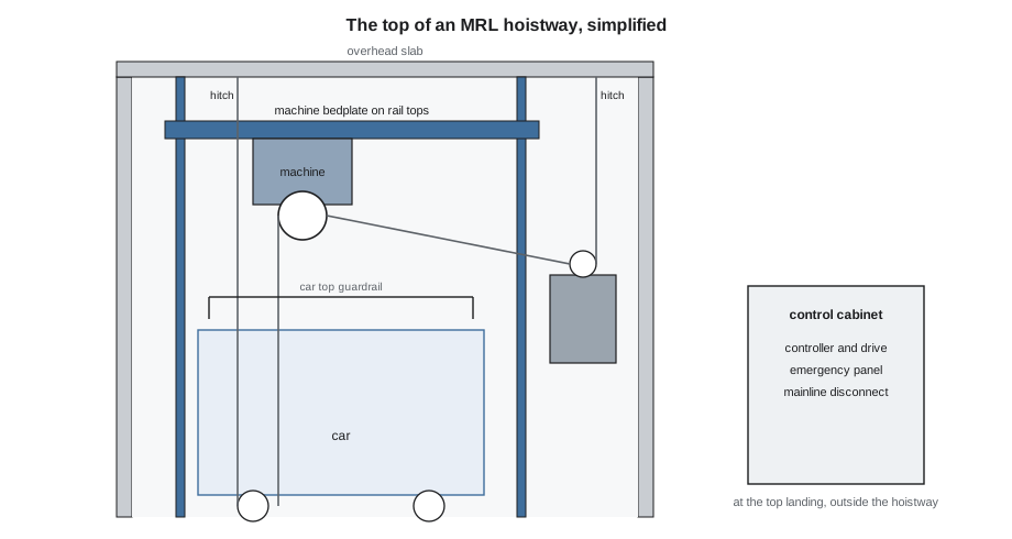
Most MRL elevators use two-to-one roping. The ropes run from a hitch at the top of the hoistway, down under a sheave on the car, up over the machine's drive sheave, down under a sheave on the counterweight, and back up to a second hitch at the top. With this arrangement, the rope tension on each side is about half the weight it carries, which lets a small machine with a small sheave do the work. It also means the overhead structure carries the hitches as well as the machine. The ropes themselves are the subject of ELV-230; here, they matter because they set the loads the machine support and hitches put into the building.
Static loads at the top of the hoistway
With two-to-one roping, each rope fall on the car side carries half the car and its load, and each fall on the counterweight side carries half the counterweight. The machine sheave has one car-side fall and one counterweight-side fall on it, and the two hitches each have one fall. The total load at the top is therefore the whole car, load and counterweight, plus the machine itself, shared between the machine support and the hitches. The calculation below shows the static share for a Quayside car with full load. The design reactions on the layout are larger, because the engineer adds the effects of acceleration, safety application and buffer strikes, and the factor used here for those is illustrative only.
# Static loads at the top of a Quayside hoistway, 2:1 roping, full car (illustrative factor)
g = 1
car, load, cwt, machine = 3300, 3500, 4875, 1320    # lb
car_fall = (car + load) / 2 * g       # tension in one car-side fall, lb
cwt_fall = cwt / 2 * g                # tension in one counterweight-side fall, lb
on_machine = car_fall + cwt_fall + machine * g
print(f"car-side fall: {car_fall:,.0f} lb   counterweight-side fall: {cwt_fall:,.0f} lb")
print(f"machine support: {on_machine:,.0f} lb static")
print(f"car hitch: {car_fall:,.0f} lb   counterweight hitch: {cwt_fall:,.0f} lb")
total = on_machine + car_fall + cwt_fall
print(f"total at the top: {total:,.0f} lb static; with an illustrative factor of 2: {2 * total:,.0f} lb")car-side fall: 3,400 lb counterweight-side fall: 2,438 lb machine support: 7,158 lb static car hitch: 3,400 lb counterweight hitch: 2,438 lb total at the top: 12,995 lb static; with an illustrative factor of 2: 25,990 lb
The total static load is the weight of everything hanging in the hoistway, as it must be. The useful lesson is how it divides: the machine support carries more than half, and each hitch carries one fall. A mechanic who knows this understands why the hitch beams in the overhead are as heavy as the machine support, and why their fastenings are inspected as carefully. The ropes, sheaves and hitch details are handled in ELV-230.
Setting the machine
An MRL machine for a car like Quayside's weighs well over a thousand pounds, and it is lifted to the top of the hoistway with the hoist on the hoist beam, under a lift plan, with nobody in the hoistway below. The rigging is the subject of ELV-130. Once the machine is landed on its support, it is set in position, leveled and aligned, then fastened. The manufacturer's installation manual gives the tolerances, and the checks are usually these.
- Position. The machine is placed so that its drive sheave is in the position the layout gives relative to the rail lines, so that the ropes drop to the car and counterweight sheaves at the right points.
- Level and plumb. The machine base is leveled and the drive sheave set plumb, using shims under the base or the adjusters the support provides, so that the ropes run true in their grooves.
- Isolation. Vibration isolation pads or mounts go between the machine and its support where the design calls for them, and nothing bridges them.
- Fastening. The machine and support bolts are tightened to torque and marked, and any seismic restraints shown on the details are fitted.
- Protection. The machine is covered until the hoistway work above is finished, because dust and concrete spatter damage brakes and encoders.
The rope hitches, the governor and its mounting, and any deflector sheaves are set at the same stage from the same lines. On an MRL elevator, the governor is often mounted at the top of the hoistway on a car rail bracket, with its rope running down to the tension sheave in the pit that was set in Lesson 8. The plumb line from the governor sheave to the tension sheave is checked so that the rope will not rub.
The control cabinet and wiring
The controller and drive of an MRL elevator sit in a cabinet outside the hoistway, at Quayside beside the top landing entrance of each car, with the emergency and inspection panel built into it. The cabinet location is on the layout and the architectural drawings, because it is in the corridor wall and must have the working clearance in front of it that the electrical code requires.
Elevator wiring in Washington follows the National Electrical Code, including Article 620 for elevators and similar equipment, as adopted by the state, along with ASME A17.1 and A17.5. The mainline disconnect for each car must be where the code puts it, within sight of the controller, and it is part of the lockout procedure from ELV-110.
Wiring between the cabinet and the machine runs in the hoistway in conduit or trunking fixed to the walls, and the traveling cable to the car is hung later. At this stage, the crew sets the cabinet, the conduit runs and the junction boxes, and the electrical work on the controller follows once the car is built.
Traditional machine rooms
On a machine-room job, or on a modernization like those on Route 7, the machine sits on steel beams or a concrete plinth in the room above the hoistway, with rope holes through the floor. The machine beams are set level and to the rope drop positions, and the machine is mounted on isolation pads. The controller, governor, disconnect and any motor-generator set are laid out with the working clearances the electrical code and elevator code require, the trap door or hoisting beam is positioned for lifting equipment in and out, and the room has its own lighting, ventilation and a door that locks. The rope holes are sized to clear the ropes without leaving a gap a tool could fall through, and they are guarded with a raised curb so that nothing on the floor can be kicked into the hoistway.
Machine room work has one big safety advantage over MRL work: the machine can be reached without being in the hoistway. Its hazards are moving sheaves and ropes at floor level, rotating machinery, and electrical equipment, and its guards and lockouts follow from ELV-110.
Working at the top of the hoistway
Setting an MRL machine and its supports puts the crew at the very top of the hoistway, under the overhead slab, often with the hoistway open below them for its full height. The work platform is the working surface, and it is positioned and locked before anything is lifted. Both workers are tied off to the lifeline on its separate anchor beam, and the hoist beam is never used as a fall protection anchor because it carries the lifts. The gaps between the platform and the walls, rails and brackets are where tools and fasteners fall, so toe boards are fitted and small parts are kept in closed containers.
At Quayside, the machine setting is a separate task on the job hazard analysis, under the written fall protection work plan required by DOSH, and Lena closes the hoistway below to all other work for the day of each machine lift.
Once the machine is set and its brake is holding, it becomes a source of hazardous energy. From the day the ropes go on, the machine is locked out at the mainline disconnect in the control cabinet whenever anyone works on it or in the hoistway, following the lockout procedure from ELV-110. Before the ropes, the crew still treats the drive sheave as a pinch point and keeps hands clear when it is turned by hand for alignment.
Common mistakes
MistakeChanging the rail base plates on an MRL job because a different size is in stock.
InsteadWhere the rails carry the machine load, the bases and pit floor are designed for it; changes need engineering review.
MistakeUsing the hoist beam as a fall protection anchor.
InsteadTie off to the lifelines on their separate anchor beam.
MistakeLeaving the machine uncovered while drilling above.
InsteadCover the machine until the hoistway work above is finished.
MistakeTreating the emergency panel as a convenience.
InsteadIt is the rescue station; its brake release and position display are life-safety equipment.
MistakeForgetting the hitches when thinking about loads at the top.
InsteadWith two-to-one roping, the hitches carry half the falls; their beams and fastenings matter as much as the machine support.
Summary and key terms
- The code distinguishes machine rooms, control rooms, and machinery and control spaces, which can be inside the hoistway.
- An MRL machine sits at the top of the hoistway on a beam, wall bracket or rail-mounted frame; the controller is in a landing cabinet.
- With two-to-one roping, the machine support and the two hitches share the weight of the car, load and counterweight.
- The machine is positioned to the rail lines, leveled, its sheave plumbed, isolated and fastened to torque.
- Electrical work follows the elevator code and the electrical code, with the disconnect within sight of the controller.
- Top-of-hoistway work is done from a locked platform, tied off to independent lifelines, with the hoistway below closed.
- Machine-room-less (MRL)
- A traction elevator with its machine inside the hoistway and its controller outside it.
- Machine room
- A separate room housing the elevator machine.
- Machinery space
- A space, which may be inside the hoistway, where elevator machinery is located.
- Two-to-one roping
- A roping arrangement in which each rope fall carries about half the suspended weight.
- Rope hitch
- The fixed end of a rope fastened to the structure or to the car or counterweight.
- Emergency panel
- A landing panel on an MRL elevator with brake release and car position display for rescue.
Practice problems
Work each problem on paper first, then reveal the answer to check.
Where is rescue of trapped passengers done on a Quayside MRL car?
Show answer
From the emergency panel in the control cabinet at the landing, outside the hoistway.
A car and its load weigh 6,000 lb on two-to-one roping. What does one car-side fall carry?
Show answer
3,000 lb.
Why may the rails of an MRL elevator be designed for vertical load?
Show answer
The machine may be mounted on the rail tops, so the rails carry its load to the pit.
Name three checks when setting an MRL machine.
Show answer
Position to the rail lines, level and sheave plumb, isolation, fastening to torque.
Lesson quiz · 5 questions
Score 60% or more to complete this lesson.
Create a free account to save your progress, take quizzes and earn a certificate.