
ELE-455 · Lesson 11 of 12 · 24 min
EMC and coexistence
The first complete TLR-2 cabinet board comes back from assembly in March. Every radio works on its own: the telemetry receiver reaches −113 dBm on the bench, the cellular module registers on the network, the BLE link connects to Leo's phone. Then Leo turns everything on at once and runs the telemetry sensitivity test while the cellular module sends a firmware log. The telemetry receiver loses 11 dB of sensitivity whenever the module transmits, and on three hopping channels it loses 6 to 9 dB all the time, even with the module idle. This lesson explains both problems and their fixes. Electromagnetic compatibility (EMC) is the ability of equipment to work in its electromagnetic environment without disturbing other equipment; coexistence is the same discipline applied to radios that must share one product.
Self-interference in a multi-radio product
A product with several radios and fast digital circuits interferes with itself in four main ways. Digital clocks and data buses produce harmonics that fall in the receive bands. A transmitter's carrier, arriving at another radio's antenna or circuit, can block it. A transmitter's broadband noise and spurious emissions, far from its own carrier, can fall in another radio's receive band. And two transmitters, or a transmitter and a strong external signal, can create intermodulation products in a nonlinear stage. Each mechanism has its own fix, and the first job is to find which one is at work.
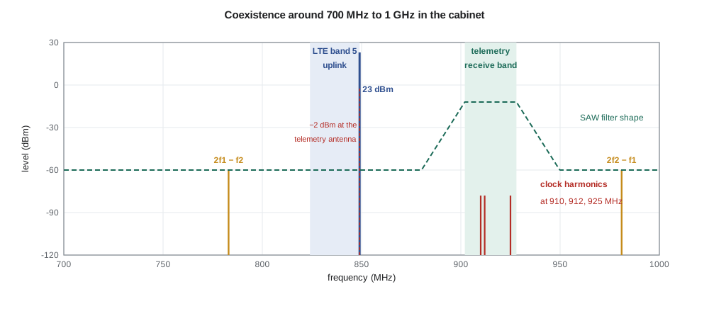
Clock harmonics: the three bad channels
Leo's three bad channels are 910.0, 912.0 and 925.0 MHz. A quick calculation finds their source: 910 MHz is the 35th harmonic of the transceiver's own 26 MHz crystal, 912 MHz the 19th harmonic of the 48 MHz main microcontroller clock, and 925 MHz the 37th harmonic of the 25 MHz Ethernet clock on the cabinet interface board. Square-wave clocks have harmonics that fall off only slowly with harmonic number, at about 20 dB per decade up to a frequency set by the edge rate and 40 dB per decade beyond, so even the 35th harmonic of a fast-edged clock can be tens of decibels above a sensitive receiver's noise floor if it couples into the front end.
import math

# 1. Clock harmonics that land in receive bands of the TLR-2 cabinet unit
clocks = {'26 MHz radio crystal': 26e6, '48 MHz microcontroller': 48e6, '25 MHz Ethernet': 25e6, '2.1 MHz buck converter': 2.1e6}
bands = {'sub-GHz 902-928': (902e6, 928e6), 'LTE band 12 downlink 729-746': (729e6, 746e6),
         'LTE band 5 downlink 869-894': (869e6, 894e6), 'BLE 2402-2480': (2402e6, 2480e6)}
for cname, fc in clocks.items():
    hits = []
    for bname, (lo, hi) in bands.items():
        n1, n2 = math.ceil(lo/fc), math.floor(hi/fc)
        if n2 >= n1: hits.append(f"{bname}: harmonics {n1}-{n2}" if n2 > n1 else f"{bname}: harmonic {n1} ({n1*fc/1e6:.1f} MHz)")
    print(f"{cname}: " + ("; ".join(hits) if hits else "none"))

# 2. LTE-M transmitter (band 5 uplink, 849 MHz edge) next to the 902-928 MHz receiver
p_tx = 23.0; iso = 25.0                  # antenna-to-antenna isolation on the roof, dB
at_rx = p_tx - iso
print(f"LTE-M carrier at the sub-GHz antenna port: {at_rx:.1f} dBm (the LNA compresses near -25 dBm at its input)")
saw_rej = 45.0                           # SAW rejection 53 MHz below the band edge
print(f"after the SAW: {at_rx - saw_rej:.1f} dBm")
# transmitter noise falling in the 902-928 MHz band
tx_noise = -135.0                        # dBm/Hz at 53+ MHz offset from the LTE PA, before its duplexer
for duplex_rej in (0.0, 20.0, 35.0):
    n = tx_noise - duplex_rej - iso + 10*math.log10(67.5e3)
    floor = -174 + 10*math.log10(67.5e3) + 2.68
    des = 10*math.log10(1 + 10**((n - floor)/10))
    print(f"  LTE duplexer gives {duplex_rej:4.1f} dB at 915 MHz: TX noise in channel {n:6.1f} dBm -> desense {des:4.1f} dB")

# 3. Third-order intermodulation between the two transmitters
f_lte, f_sub = 849e6, 915e6
for name, f in (("2f1 - f2", 2*f_lte - f_sub), ("2f2 - f1", 2*f_sub - f_lte), ("f1 + f2", f_lte + f_sub)):
    print(f"  {name}: {f/1e6:7.1f} MHz")

# 4. Shielding needed: microcontroller noise radiated at 912 MHz (19th harmonic of 48 MHz)
pick = -78.0                              # coupled level at the LNA input without a shield, dBm in 67.5 kHz
target = -174 + 10*math.log10(67.5e3) + 2.68 - 6.0   # 6 dB below the noise floor
print(f"shield and filtering must provide {pick - target:.1f} dB at 912 MHz")26 MHz radio crystal: sub-GHz 902-928: harmonic 35 (910.0 MHz); LTE band 5 downlink 869-894: harmonic 34 (884.0 MHz); BLE 2402-2480: harmonics 93-95 48 MHz microcontroller: sub-GHz 902-928: harmonic 19 (912.0 MHz); BLE 2402-2480: harmonic 51 (2448.0 MHz) 25 MHz Ethernet: sub-GHz 902-928: harmonic 37 (925.0 MHz); LTE band 5 downlink 869-894: harmonic 35 (875.0 MHz); BLE 2402-2480: harmonics 97-99 2.1 MHz buck converter: sub-GHz 902-928: harmonics 430-441; LTE band 12 downlink 729-746: harmonics 348-355; LTE band 5 downlink 869-894: harmonics 414-425; BLE 2402-2480: harmonics 1144-1180 LTE-M carrier at the sub-GHz antenna port: -2.0 dBm (the LNA compresses near -25 dBm at its input) after the SAW: -47.0 dBm LTE duplexer gives 0.0 dB at 915 MHz: TX noise in channel -111.7 dBm -> desense 11.6 dB LTE duplexer gives 20.0 dB at 915 MHz: TX noise in channel -131.7 dBm -> desense 0.6 dB LTE duplexer gives 35.0 dB at 915 MHz: TX noise in channel -146.7 dBm -> desense 0.0 dB 2f1 - f2: 783.0 MHz 2f2 - f1: 981.0 MHz f1 + f2: 1764.0 MHz shield and filtering must provide 51.0 dB at 912 MHz
The program searches all the clocks on the board against all the receive bands. Besides the three telemetry channels, the 26 MHz and 25 MHz clocks have harmonics in the LTE band 5 downlink at 884 and 875 MHz, the 48 MHz clock has its 51st harmonic at 2448 MHz in the BLE band, and the 2.1 MHz switching converter, whose fast edges produce a comb of harmonics every 2.1 MHz, places lines across every band. The cellular module and the BLE chip are sensitive receivers too, and a clock harmonic that falls on the cellular downlink can reduce the module's sensitivity just as surely.
Leo measures the 912 MHz harmonic at −78 dBm in the receiver's 67.5 kHz bandwidth at the LNA input with no shield in place. To make it harmless, it must be at least 6 dB below the receiver's −123 dBm noise floor, at −129 dBm, so shielding and filtering must provide 51 dB at 912 MHz. The fixes, in order of preference, are to stop the noise at its source, to keep it from coupling, and to keep the receiver from being affected.
At the source, the microcontroller's clock output and the fastest data lines get series resistors that slow their edges, and the switching converter gets a spread-spectrum clock that smears its harmonics over a band rather than concentrating them in lines. On the coupling path, the microcontroller and memory are placed at the far side of the board from the telemetry front end, every trace leaving them is routed over solid ground, never across a split, and the telemetry front end gets its own shield can with a continuous fence of ground vias around it; Leo measures 40 dB of isolation from the can and 15 dB more from the layout changes. At the receiver, removing channels 15, 19 and 45 from the hopping sequence is tempting, but with narrow hopping channels the rules require at least 50 channels, and the cabinet would be left with 47. Amara keeps all 50 channels and moves the clocks instead.
Retuning works because harmonics move with the clock. Changing the transceiver crystal from 26 MHz to 26.4 MHz would move its 35th harmonic to 924 MHz, still in band, so instead Priya chooses a reference frequency whose harmonics fall between channels, away from any channel's 67.5 kHz bandwidth. With a 30 MHz crystal, harmonics fall at 900 and 930 MHz, both outside the band; the telemetry transceiver supports a 30 MHz reference, and the synthesizer of lesson 7 simply uses different divide ratios. Its 29th harmonic, 870 MHz, lands at the bottom edge of the LTE band 5 downlink, which the transceiver's shield can must contain. The microcontroller moves to a 50 MHz clock, whose harmonics fall at 900 and 950 MHz. Only the Ethernet clock is fixed by its standard, and its 925 MHz harmonic is the one handled by shielding alone.
Blocking by the LTE-M transmitter
The 11 dB loss of sensitivity while the module transmits has a different cause. The module transmits up to 23 dBm. In LTE band 5 its uplink extends to 849 MHz, only 53 MHz below the telemetry band. With the two antennas 25 dB apart, the program calculates that the LTE carrier arrives at the telemetry antenna port at −2 dBm. The LNA compresses near −25 dBm at its input, so without the SAW filter in front of it the LNA would be badly blocked. The SAW, with about 45 dB of rejection at 849 MHz, brings the carrier down to −47 dBm, which the LNA handles without trouble. Blocking by the carrier is therefore not the problem, which is exactly why lesson 1 put the SAW first.
The problem is the transmitter's noise. Any power amplifier produces broadband noise and modulation sidebands far from its carrier. At 53 MHz or more from the LTE carrier, Leo measures the module's noise density at about −135 dBm/Hz at its antenna port with the module's own filtering bypassed, and the program shows the consequence. If nothing in the module's transmit path attenuates noise at 915 MHz, the noise reaching the telemetry receiver in its 67.5 kHz bandwidth is −111.7 dBm, 11 dB above the receiver's noise floor: an 11.6 dB desensitization, exactly the problem Leo saw. That noise falls inside the telemetry band, so the SAW filter cannot remove it; it must be stopped at the transmitter. The module's internal duplexer gives about 20 dB of rejection at 915 MHz, reducing the desensitization to 0.6 dB; with 35 dB it would vanish.
Why, then, did Leo see 11 dB? The module's data sheet says its duplexer rejects 915 MHz, but the module maker's reference design, which Cedarline copied, routes the antenna connection through a test connector placed before the duplexer for production testing. On the TLR-2 board the antenna had been connected to that test point. Moving the antenna connection to the correct pad fixes the problem, and the measured desensitization falls to under 1 dB. The lesson the team records is that coexistence numbers depend on details that block diagrams hide.
Worked problem
Isolation needed for a 1 dB desensitization limit
Measured at the test connector before the duplexer, the module's transmit noise near 915 MHz is −135 dBm/Hz. The telemetry receiver's floor is −123.0 dBm in 67.5 kHz. How much total isolation between the module's amplifier and the telemetry receiver keeps the desensitization under 1 dB, and how much of it must the duplexer provide if the antennas give 25 dB?
Show solution
- A 1 dB rise in the floor means the interference must be about 5.9 dB below the receiver's own noise.
- \[P_{int,max} = -123.0 - 5.9 = -128.9\ \text{dBm}\]
- \[P_{noise} = -135 + 10\log_{10}(67\,500) = -86.7\ \text{dBm in the telemetry channel}\]
- \[\text{Isolation} = -86.7 - (-128.9) = 42.2\ \text{dB}\]
- The antennas provide 25 dB, so the duplexer must provide at least 17 dB at 915 MHz.
Answer: About 42 dB in total, of which at least 17 dB must come from the module's duplexer.
The example shows how much the answer depends on where each number is referenced, and Amara insists that every coexistence calculation state where each noise density and rejection figure applies. With the corrected connection, the noise density at the module's antenna connector, after its duplexer, is about −155 dBm/Hz, and with 25 dB of antenna isolation the desensitization is about 0.6 dB, the program's second case.
Intermodulation between transmitters
When the cellular module and the telemetry transmitter transmit at the same time, each transmitter's signal reaches the other's power amplifier through the antennas. A power amplifier's output stage is nonlinear, and a signal entering its output can mix with its own carrier, a mechanism called reverse intermodulation. The program lists the third-order products of an LTE carrier at 849 MHz and the telemetry carrier at 915 MHz: 2f₁ − f₂ = 783 MHz, close to LTE band 13's uplink and band 12's downlink, and 2f₂ − f₁ = 981 MHz. The second-order sum, 1764 MHz, falls in the AWS uplink band. Each of these is an unwanted emission that must meet the out-of-band limits, and the products near the cellular downlinks can reduce the module's sensitivity. The cure is isolation between antennas, plus coordination in time: the cabinet firmware avoids starting a telemetry transmission while the cellular module is transmitting a long message, using a status line from the module. Short, rare overlaps remain, and Leo measures their products at the regulatory test to confirm they meet the limits.
Coexistence at 2.4 GHz
BLE shares 2.4 GHz with Wi-Fi, microwave ovens and other devices. BLE's adaptive frequency hopping marks channels where it detects interference and stops using them, and its three advertising channels sit between the most common Wi-Fi channels. In a cabinet near a coffee shop's Wi-Fi access point, the maintenance link still works, but connections may take a little longer. Since the BLE link is used only during maintenance and carries little data, no further measures are needed.
EMC beyond the radios
The product as a whole must also meet EMC requirements that have nothing to do with its own radios. Its digital circuits must not radiate or conduct emissions above the limits for unintentional radiators. It must tolerate electrostatic discharge, radiated fields from nearby transmitters such as the city's own truck radios, electrical fast transients on its power and signal cables and surges from lightning, which ELE-360 touched on for the push button. Traffic equipment has its own environmental and electrical standards set by transportation agencies, and Cedarline's existing cabinet products already pass them; TLR-2 inherits the cabinet interface design, and the new radios mainly change the radiated immunity picture because their antenna ports offer a direct path into the electronics. Each radio input is protected with the ESD and surge measures of ELE-360, and a quarter-wave shorted stub, which is a short circuit at DC and lightning frequencies but an open circuit at 915 MHz, protects the telemetry antenna port.
Common mistakes
MistakeTesting each radio alone and assuming they will work together.
InsteadClock harmonics, transmitter noise and intermodulation appear only with everything running; test the full product.
MistakeExpecting a receive filter to remove another transmitter's noise in the receive band.
InsteadNoise inside the receive band passes the filter; it must be filtered at the transmitter or reduced by isolation.
MistakeRemoving interfered channels from a hopping sequence without checking the rules.
InsteadFrequency-hopping rules set a minimum number of channels; retuning clocks may be the better fix.
MistakeQuoting coexistence numbers without saying where they apply.
InsteadA noise density before or after a duplexer can differ by tens of decibels; state the reference point.
Summary and key terms
- Self-interference comes from clock harmonics, transmitter blocking, transmitter noise in other bands and intermodulation.
- Clock harmonics can be fixed at the source (edge rate, spread spectrum, frequency choice), on the path (layout, shielding) or at the receiver.
- A filter before the LNA protects against out-of-band carriers; noise inside the receive band must be stopped at the transmitter.
- Required isolation follows from the interferer level and the allowed rise in noise floor; 1 dB desensitization needs interference about 6 dB below the floor.
- Reverse intermodulation between transmitters creates products that must meet emission limits; time coordination helps.
- The whole product must meet emission and immunity requirements, including protection of antenna ports.
- Electromagnetic compatibility (EMC)
- The ability of equipment to work in its environment without disturbing others.
- Coexistence
- The ability of several radios to operate together in one product or place.
- Desensitization
- Loss of receiver sensitivity caused by an interfering signal or noise.
- Spread-spectrum clocking
- Modulating a clock frequency slightly to spread its harmonics over a band.
- Shield can
- A grounded metal enclosure over part of a circuit board.
- Reverse intermodulation
- Mixing in a power amplifier of its own carrier with a signal entering its output.
- Antenna isolation
- The coupling loss between two antennas' ports.
- Duplexer
- A filter that separates transmit and receive bands sharing one antenna.
Practice problems
Work each problem on paper first, then reveal the answer to check.
Which harmonic of a 40 MHz clock falls in 902–928 MHz?
Show answer
The 23rd, at 920 MHz.
A receiver's floor is −120 dBm. What interference level causes 3 dB of desensitization?
Show answer
−120 dBm, equal to the floor.
Why does a SAW filter not remove LTE transmitter noise that falls at 915 MHz?
Show answer
The noise is inside the SAW's passband.
Find the third-order products of carriers at 830 and 915 MHz.
Show answer
745 MHz and 1000 MHz.
Give three ways to reduce a clock harmonic in a receive band.
Show answer
Slow the clock edges, use spread-spectrum clocking or a different frequency, add shielding and better layout.
Why does the cabinet firmware avoid simultaneous transmissions where it can?
Show answer
To avoid reverse intermodulation products and desensitization during overlaps.
Lesson quiz · 5 questions
Score 60% or more to complete this lesson.
Create a free account to save your progress, take quizzes and earn a certificate.