
ELE-315 · Lesson 11 of 12 · 24 min
Low-power design and power management
A desktop processor that wastes a watt costs its owner a few dollars a year. A sensor node that wastes a milliamp may need a battery twice as large, a solar panel that blows off the pole in the first winter storm, or a technician's visit every few months. For battery and energy-harvesting devices, energy is the constraint that shapes everything else: the choice of microcontroller, the clock rate, the structure of the firmware and even the protocol on the radio. Lesson 1 estimated the NS-4's energy budget in a single line. This lesson builds that estimate properly, explains where the power in a digital system goes, shows how sleep modes, clocking and duty cycling cut it, and covers the hardware details, from pull-up resistors to battery chemistry, that firmware engineers must watch.
The NS-5 will add on-node classification, a faster SPI link, a short-range radio and a CAN interface for the cabinet version. Ines Carvalho, the hardware lead, has a firm limit: the pole-top node must keep the NS-4's 24 Ah battery and 40 W panel, and still run five days without sun in a northern January. Jonah's task is to write the power budget, find the savings, and turn them into firmware.
Where the power goes
The power of a CMOS digital circuit has two parts. Dynamic power is spent charging and discharging capacitances each time a node switches; it is proportional to the switched capacitance, the square of the supply voltage and the switching frequency. Static power is leakage through transistors that are nominally off; it depends on the process, the supply voltage and strongly on temperature, and it flows whether or not anything is happening. On a modern microcontroller, running current scales roughly linearly with clock frequency, typically 50 to 150 µA per MHz, while deep-sleep current is set by leakage and by whatever stays powered: the real-time clock, a little RAM, and the brownout detector.
The quadratic dependence on voltage is why microcontrollers run their cores from internal regulators at 1.0 to 1.2 V even when the pins run at 3.3 V, and why some offer several voltage ranges: a lower core voltage saves power but limits the maximum clock. The NS-4's microcontroller, for example, allows 48 MHz in its high-performance range and 24 MHz in its low-power range.
Sleep modes
Every low-power microcontroller provides a ladder of modes that turn off progressively more of the chip. The details and names vary between families, but the pattern is common.
| Mode | What stops | What keeps running | Typical current | Typical wake time |
|---|---|---|---|---|
| Run | Nothing | Core, clocks, enabled peripherals | 50 to 150 µA per MHz | - |
| Sleep (idle) | Core clock | Peripherals, DMA, interrupts | About a third of run | A few cycles |
| Stop (deep sleep) | High-speed clocks and most peripherals | RAM, registers, low-power timer, RTC, some wake pins | 1 to 10 µA | 5 to 50 µs |
| Standby | Core regulator and most RAM | RTC, backup registers, wake pins | 0.2 to 1 µA | Like a reset, about 1 ms |
| Shutdown | Almost everything | Wake pins only | Tens of nA | Full reset |
The trade-offs are wake time and state. Sleep keeps everything and wakes instantly, but saves little. Stop keeps RAM and registers, so the firmware resumes where it left off, but the high-speed oscillator and PLL must restart, which takes tens of microseconds, and only certain peripherals, such as a low-power timer, a low-power UART, the RTC and pin interrupts, can run and wake the core. Standby and shutdown lose RAM, so waking is a reset; firmware must save what it needs in backup registers or nonvolatile memory. For a node that wakes many times a second, stop mode is the usual working state; for a node that wakes once an hour, standby may win.
Duty cycling and the power budget
The average current of a device that alternates between states is the time-weighted sum of each state's current. A power budget lists every load, its current in each state and the fraction of time it spends there. It is the single most useful document in low-power design, because it shows at once which loads matter: almost always one or two dominate, and optimizing anything else is wasted effort.
# NS-4 and NS-5 power budgets: average current on the 3.3 V rail and battery life
V_rail, V_bat, eff = 3.3, 12.8, 0.85
def budget(loads):
    total = 0.0
    for name, states in loads.items():
        i_avg = sum(i_ma * duty for i_ma, duty in states)
        total += i_avg
        print(f"  {name:34s} {i_avg:7.3f} mA")
    return total
ns4 = {
    "MCU, memory (run and light sleep)": [(5.0, 0.10), (0.78, 0.90)],
    "radar module, continuous": [(9.0, 1.0)],
    "modem, hourly upload": [(2.5, 1.0)],
    "I2C pull-ups (traffic)": [(3.0, 0.01)],
}
ns5 = {
    "MCU, stop mode between frames": [(6.5, 0.12), (0.004, 0.88)],
    "radar, low-power presence mode": [(9.0, 0.35), (3.0, 0.65)],
    "modem, batched 4-hourly + PSM": [(0.9, 1.0)],
    "short-range radio, on tamper only": [(0.008, 1.0)],
    "I2C pull-ups (traffic)": [(3.0, 0.01)],
}
# The battery divider and the heater draw from the battery directly, not from the rail
products = (("NS-4", ns4, 0.096, 0.20), ("NS-5", ns5, 0.096 * 1e-3 / 60, 0.10))
for name, loads, divider_ma, heater_duty in products:
    print(name)
    i_rail = budget(loads)
    i_bat = i_rail * V_rail / (V_bat * eff) + divider_ma
    print(f"  rail {i_rail:.2f} mA -> battery {i_bat:.2f} mA including divider {divider_ma:.6f} mA")
    for season, derate, heater_ma in (("summer", 1.0, 0.0), ("January", 0.7, 35.0 * heater_duty)):
        i = i_bat + heater_ma
        hours = 24 * derate / (i / 1000)
print(f" {season:8s}: battery current {i:5.2f} mA, about {hours/24:5.0f} days on a full charge")NS-4 MCU, memory (run and light sleep) 1.202 mA radar module, continuous 9.000 mA modem, hourly upload 2.500 mA I2C pull-ups (traffic) 0.030 mA rail 12.73 mA -> battery 3.96 mA including divider 0.096000 mA summer : battery current 3.96 mA, about 253 days on a full charge January : battery current 10.96 mA, about 64 days on a full charge NS-5 MCU, stop mode between frames 0.784 mA radar, low-power presence mode 5.100 mA modem, batched 4-hourly + PSM 0.900 mA short-range radio, on tamper only 0.008 mA I2C pull-ups (traffic) 0.030 mA rail 6.82 mA -> battery 2.07 mA including divider 0.000002 mA summer : battery current 2.07 mA, about 483 days on a full charge January : battery current 5.57 mA, about 126 days on a full charge
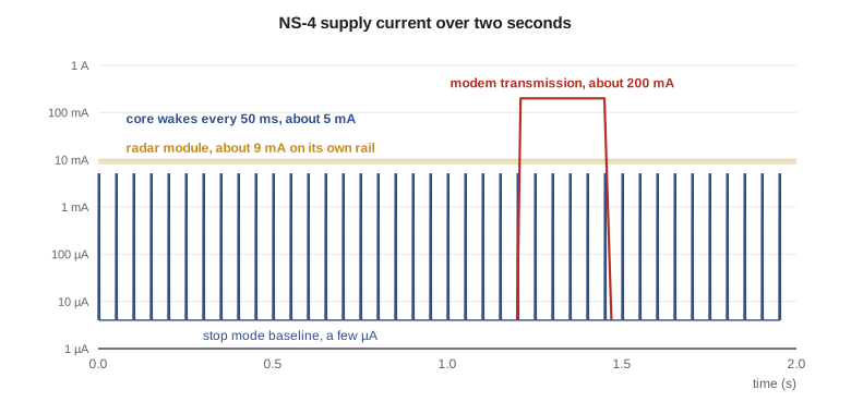
The numbers tell Jonah where to work. On the NS-4, the radar draws 9 mA continuously, about 70 percent of the rail, and the modem 2.5 mA. The microcontroller averages 1.2 mA, the figure lesson 1 used, because the old firmware uses only the light sleep mode and never stop. In January the heater, which keeps the battery warm enough to accept charge, adds an average of 7 mA at the battery, more than everything else together. The NS-5 budget cuts the rail current roughly in half: the radar module's presence mode, which runs at full rate only while a vehicle is near, batched uploads with the modem's power-saving mode, and stop mode between frames, which keeps the microcontroller's average low even though classification makes it work harder. The heater is Ines's problem, and she moves to a better-insulated battery box that halves its duty in the NS-5. Both nodes far exceed the five-day requirement on a full charge; the margin is what carries a node through weeks of short, dull days when the panel cannot fully recharge the battery.
Race to sleep
Should a device run fast and sleep sooner, or run slowly and stay awake longer? Because dynamic energy per operation is nearly independent of clock frequency, while static current and the fixed overheads of an awake chip, such as regulators, oscillators and flash, are paid for as long as the chip is awake, running fast and returning to deep sleep usually wins. This strategy is called race to sleep. It fails when the work is waiting rather than computing, for example polling a slow peripheral, or when the fast clock's PLL takes long to start.
Worked problem
Race to sleep for the radar frame processing
Each second, the NS-5 must execute 480,000 cycles of processing. At 48 MHz the microcontroller draws 5.0 mA; at 8 MHz, from its internal oscillator without the PLL, it draws 1.4 mA. In stop mode it draws 2 µA. Compare the average current of the two choices.
Show solution
- \[ t_{48} = \frac{480000}{48\ \text{MHz}} = 10\ \text{ms}, \qquad t_{8} = \frac{480000}{8\ \text{MHz}} = 60\ \text{ms}\]
- \[ \bar I_{48} = 0.010 \times 5.0 + 0.990 \times 0.002 = 0.0520\ \text{mA}\]
- \[ \bar I_{8} = 0.060 \times 1.4 + 0.940 \times 0.002 = 0.0859\ \text{mA}\]
Answer: Running at 48 MHz and sleeping uses about 40 percent less charge, because the 8 MHz case pays for the chip's static and overhead current six times as long. Measuring both is still worth doing, since the result depends on the chip.
Tickless operation and wake sources
Firmware structure has a large effect on power. A system tick that interrupts 1,000 times a second, as in lesson 6, wakes the core 1,000 times a second even when there is nothing to do. Each wake costs entry and exit time, oscillator restart and some flash reads. Tickless operation programs a low-power timer to wake the core only at the next scheduled event, and the scheduler corrects its notion of time on wake from the timer's count. Real-time operating systems usually support tickless idle; in a superloop design, the main loop computes the next deadline itself before entering stop mode.
/* Main-loop idle with tickless sleep: wake at the next deadline or on any interrupt. */
void idle(void)
{
    uint32_t now  = lptim_now_ms();
    uint32_t next = sched_next_deadline_ms();          /* earliest software timer */
    if ((int32_t)(next - now) <= 1) return;            /* too soon to bother sleeping */

    __disable_irq();                                    /* close the race with pending work */
    if (!work_pending()) {
        lptim_set_compare(next);
        enter_stop_mode();                              /* WFI with deep sleep selected */
        clocks_restore_after_stop();                    /* restart high-speed oscillator and PLL */
    }
    __enable_irq();                                     /* pending interrupts run here */
}
The masked check in that listing deals with a classic low-power race. If an interrupt arrives after the main loop decides there is no work but before it sleeps, the core would sleep with work pending, perhaps until the next timer event. Masking interrupts, checking, then executing the wait-for-interrupt instruction closes the window, because a pending interrupt still wakes the core from the wait even when masked, and is serviced once interrupts are enabled again.
Wake sources must be chosen with care. In stop mode, only some peripherals run; the NS-5 relies on the low-power timer, the radar module's interrupt line, the RTC alarm, the tamper switch and a low-power UART that can wake on a start bit. Peripherals that need a high-speed clock, such as the main SPI controller, cannot run in stop mode, so a transfer must complete before the core sleeps, or DMA must be arranged to run in sleep mode instead.
The hidden currents
Once the core sleeps properly, small leaks become visible. Jonah's first measurement of an NS-5 prototype in stop mode reads 410 µA instead of the expected 4 µA. Finding the difference is a standard exercise, and the culprits are standard too.
| Source | Mechanism | Typical waste | Fix |
|---|---|---|---|
| Floating inputs | An input pin near mid-supply turns both input transistors partly on | Tens to hundreds of µA per pin | Configure unused pins as analog or with a pull |
| Pull-up held low | A pull-up resistor against a pin driven or held low | 3.3 V ÷ R, e.g. 330 µA for 10 kΩ | Release lines or drive them high before sleep |
| Resistor dividers | A battery-sense divider always connected | V ÷ (R1 + R2), e.g. 96 µA | Switch the divider or use high values with a capacitor |
| Peripherals left on | An ADC, comparator or reference left enabled | Tens to hundreds of µA | Disable before sleep |
| Debug interface | A connected debugger keeps clocks running | Milliamps | Measure with the debugger disconnected |
| External chips | Sensors and memories not in their own sleep modes | Microamps to milliamps | Command them to sleep or switch their supply |
The prototype's 410 µA is three of these at once. The battery divider, 100 kΩ and 33 kΩ across 12.8 V, draws 96 µA; Ines adds a transistor so the firmware switches it on for one millisecond per reading. A 10 kΩ pull-up on the radar module's interrupt line is held low by the radar in its idle state, wasting 330 µA, which a firmware change to the module's interrupt polarity fixes. Three unused pins left as floating inputs account for most of the rest. After the fixes, the board reads 4.6 µA in stop mode.
Worked problem
Switching the battery divider
The battery-sense divider uses 100 kΩ and 33 kΩ across 12.8 V. Find its continuous current. If firmware enables it for 1 ms once a minute instead, what is the average?
Show solution
- \[ I = \frac{12.8\ \text{V}}{133\ \text{k}\Omega} = 96\ \mu\text{A}\]
- \[ D = \frac{1\ \text{ms}}{60\ \text{s}} = 1.67 \times 10^{-5}\]
- \[ \bar I = 96\ \mu\text{A} \times 1.67 \times 10^{-5} = 1.6\ \text{nA}\]
Answer: Switching cuts the divider's cost from 96 µA, about 0.8 Ah per year, to a negligible 1.6 nA. The ADC input needs a small capacitor so the reading settles quickly after the switch closes.
Measuring power
Low-power design depends on measurement. A multimeter in series reads average current but cannot see microsecond wake-ups or follow a range of six orders of magnitude, from 2 µA to 200 mA. Dedicated current profilers and source-measure units sample at high rates with automatic range switching and integrate charge over time; a simpler method is a shunt resistor and an oscilloscope, with care over the shunt's voltage drop. Firmware can help by toggling a spare pin on entering and leaving each state, so a logic analyzer shows the state timeline next to the current trace. Jonah keeps a nightly test that runs the prototype through a scripted day and fails the build if the average current rises more than 5 percent.
Supplies, batteries and harvesting
The power system around the microcontroller matters as much as the firmware. Linear regulators waste the voltage difference as heat, so from 12.8 V to 3.3 V a linear regulator is only about 26 percent efficient; switching regulators reach 85 to 95 percent at moderate loads but lose efficiency at very light loads unless they have a low-power mode, and their quiescent current can exceed the sleeping microcontroller's. A brownout detector resets the microcontroller cleanly if the supply sags, and firmware should record brownout resets, since frequent ones point to a failing battery or a supply that cannot handle load steps such as a modem transmission.
Battery chemistry sets limits too. Lithium iron phosphate batteries, like the NS-4's 12.8 V pack, tolerate many cycles and are relatively safe, but must not be charged below about 0 °C, which is why the node has a heater; their usable capacity also falls in the cold. Primary lithium cells suit devices that run for years without harvesting but have high internal resistance at low temperature, so pulse loads such as radio bursts need a buffer capacitor. Energy harvesting from solar, vibration or temperature differences needs a charger that tracks the source's maximum power point and firmware that adapts its duty cycle to the energy actually available, for example by reducing upload frequency after several dull days.
Common mistakes
MistakeOptimizing a load that does not dominate the budget.
InsteadWrite the power budget first; work on the one or two largest items.
MistakeAssuming that a slower clock always saves energy.
InsteadCompare total charge; race to sleep usually wins when static and overhead current are significant.
MistakeLeaving pins floating or pull-ups held low in sleep.
InsteadConfigure every pin for sleep, and measure sleep current on every board revision.
MistakeMeasuring sleep current with a debugger attached.
InsteadDisconnect the debugger, or use a debug mode that allows real sleep.
MistakeSleeping with work pending because of a race with an interrupt.
InsteadMask interrupts, check for work, then wait for an interrupt.
Summary and key terms
- CMOS power has dynamic and static parts; dynamic power grows with voltage squared and frequency.
- Sleep, stop, standby and shutdown modes trade wake time and retained state for current.
- A power budget of currents and duty cycles shows which loads dominate.
- Race to sleep usually beats running slowly, because static and overhead current are paid while awake.
- Tickless operation and careful wake-source design avoid needless wake-ups.
- Floating pins, held-low pull-ups, dividers and forgotten peripherals cause most sleep-current surprises.
- Regulators, brownout detection, battery chemistry and harvesting complete the power system.
- Dynamic power
- Power spent switching capacitances, proportional to C·V²·f.
- Leakage
- Current through transistors that are nominally off.
- Stop mode
- A deep-sleep mode that keeps RAM and registers but stops high-speed clocks.
- Duty cycle
- The fraction of time a load spends in a given state.
- Power budget
- A table of loads, currents and duty cycles giving average current and battery life.
- Race to sleep
- Running fast to finish work and return to sleep sooner.
- Tickless idle
- Sleeping until the next scheduled event instead of waking at every tick.
- Brownout detector
- A circuit that resets the device when the supply voltage falls too low.
Practice problems
Work each problem on paper first, then reveal the answer to check.
A node draws 8 mA for 30 ms every 10 s and 3 µA otherwise. What is its average current?
Show answer
0.003 × 8 mA + 0.997 × 0.003 mA ≈ 0.027 mA.
How long would a 2.4 Ah cell last at that current, ignoring derating?
Show answer
2.4 Ah ÷ 0.027 mA ≈ 89,000 h, about 10 years; in practice self-discharge and derating would limit it.
A 4.7 kΩ pull-up is held low during sleep on a 3.3 V rail. What current does it waste?
Show answer
3.3 ÷ 4,700 ≈ 0.70 mA.
Why does a linear regulator from 12.8 V to 3.3 V waste most of the power?
Show answer
Its efficiency is at best 3.3 ÷ 12.8 ≈ 26 percent; the rest is dissipated as heat.
Lesson quiz · 5 questions
Score 60% or more to complete this lesson.
Create a free account to save your progress, take quizzes and earn a certificate.