
ELE-315 · Lesson 10 of 12 · 22 min
CAN, USB and wireless links
UART, SPI and I²C connect chips and nearby boards. Many embedded systems also need links that are more robust, more standardized or free of wires altogether. The controller area network, CAN, carries messages between dozens of control units in vehicles, machines and building systems, with priorities, error detection and fault confinement built into the hardware. The universal serial bus, USB, connects embedded devices to computers with standard classes that need no custom drivers. And wireless links, from short-range personal-area radios to cellular networks, connect devices that cannot be cabled at all. Each of these is a large subject in its own right; this lesson explains the principles an embedded engineer needs to choose and use them, with enough detail to configure CAN bit timing, reason about CAN latency, understand USB enumeration and estimate a radio link budget.
The NS-5 brings all three to Northway Sensing. The cabinet version of the NS-5 controller will connect up to eight sensor heads, radar units and inductive loop interfaces mounted around an intersection, over a 30 m CAN bus. It will replace the old RS-485 cabinet adapter with a USB service port that a technician's laptop recognizes as a serial device. And the pole-top node will add a short-range radio so that Dev Okafor, the field technician, can check a unit from the ground with a phone instead of climbing to it.
CAN: a bus for control messages
CAN is a differential, multidrop bus on a twisted pair, CAN high and CAN low, terminated with 120 Ω at each end like RS-485. Its signaling has two states: dominant, when a transceiver drives the pair apart, representing 0, and recessive, when no one drives and termination pulls the pair together, representing 1. Like I²C's open-drain lines, the bus is a wired-AND: if any node sends dominant, the bus is dominant. Classical CAN runs at up to 1 Mbit/s, with 500 kbit/s and 250 kbit/s common in vehicles and machines, and carries frames of up to 8 data bytes. CAN FD raises the data-phase rate to several megabits per second and the payload to 64 bytes, and the newer CAN XL goes further.
CAN frames are not addressed to a destination. Each carries an identifier, 11 bits in the standard format or 29 in the extended format, that names the message's content, such as 'lane 2 detection' or 'loop interface status'. Every node receives every frame and uses hardware acceptance filters to keep only the identifiers it cares about. The identifier also sets the message's priority: a lower numeric value wins arbitration.
Arbitration, priority and latency
Any node may start a frame when the bus is idle. If two start together, they arbitrate bit by bit during the identifier. Each node monitors the bus while it sends. A node sending a recessive 1 that sees a dominant 0 knows a higher-priority frame is on the bus, stops transmitting and becomes a receiver. The node with the lowest identifier never sees a mismatch and completes its frame undisturbed. No time is lost to collisions, unlike early Ethernet, and the highest-priority message always gets through first.
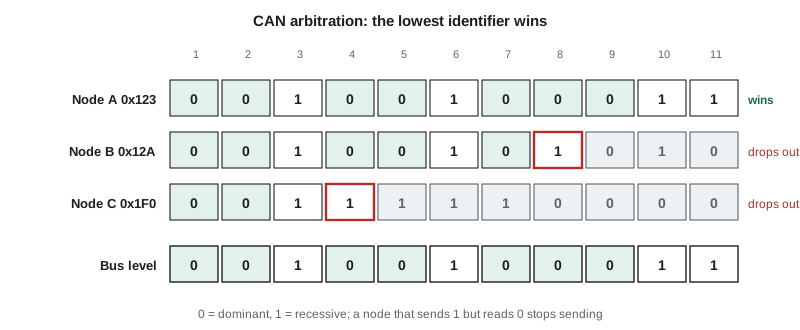
# CAN bitwise arbitration: dominant 0 overrides recessive 1 on a wired-AND bus
def arbitrate(ids, bits=11):
    active = set(ids)
    for b in range(bits - 1, -1, -1):
        sent = {i: (i >> b) & 1 for i in active}
        bus = min(sent.values())                 # any dominant 0 makes the bus 0
        lost = [i for i in active if sent[i] == 1 and bus == 0]
        for i in lost:
            print(f"  bit {bits-1-b}: 0x{i:03X} sends 1, sees 0, drops out")
        active -= set(lost)
    return active.pop()
ids = [0x123, 0x12A, 0x1F0]
print("winner:", hex(arbitrate(ids)))

# Worst-case standard frame length with bit stuffing, and its time at 500 kbit/s
def frame_bits(n):
    base = 47 + 8 * n                            # standard frame, n data bytes
    stuff = (34 + 8 * n - 1) // 4                # worst-case stuff bits
    return base + stuff
for n in (0, 2, 8):
    b = frame_bits(n)
print(f"{n} data bytes: up to {b} bits = {b/500e3*1e6:.0f} us at 500 kbit/s")bit 3: 0x1F0 sends 1, sees 0, drops out bit 7: 0x12A sends 1, sees 0, drops out winner: 0x123 0 data bytes: up to 55 bits = 110 us at 500 kbit/s 2 data bytes: up to 75 bits = 150 us at 500 kbit/s 8 data bytes: up to 135 bits = 270 us at 500 kbit/s
Because a frame cannot be interrupted once it has won arbitration, the worst-case latency of a CAN message is the time for one lower-priority frame already on the bus to finish, plus the time for all higher-priority messages that become ready meanwhile, plus its own transmission. A worst-case 8-byte frame at 500 kbit/s takes 270 µs. This is the basis of CAN response-time analysis, which lets designers prove that every message meets its deadline when the bus load and message periods are known. The NS-5 gives detection messages the lowest identifiers, status messages higher ones, and diagnostic and firmware-update traffic the highest, so that a technician downloading a log cannot delay a detection by more than one frame.
Framing, bit stuffing and error handling
A classical CAN data frame contains a start-of-frame bit, the identifier, a remote-request bit, control bits including a 4-bit data length code, up to 8 data bytes, a 15-bit cyclic redundancy check, an acknowledge slot and an end-of-frame field. Because receivers resynchronize their bit timing on recessive-to-dominant edges, the transmitter inserts an opposite stuff bit after any five identical bits, guaranteeing frequent edges; receivers remove them. The acknowledge slot is sent recessive by the transmitter and driven dominant by every receiver that got the frame correctly, so the sender knows at least one node received it.
CAN's error handling is one of its great strengths. Every node checks every frame for bit errors, stuffing errors, CRC errors, form errors and missing acknowledgment. A node that detects an error sends an error frame that deliberately violates the stuffing rule, which makes every node discard the frame, and the transmitter automatically retries. Each node keeps transmit and receive error counters, incremented on errors and decremented on successes. A node whose counter passes 127 becomes error-passive and can no longer destroy others' frames with active error flags; past 255 it goes bus-off and stops transmitting entirely. This fault confinement stops one failing node, perhaps with a broken transceiver, from bringing down the whole bus. Firmware should monitor these counters and states and report them.
CAN bit timing
A CAN controller divides each bit into time quanta derived from its clock by a prescaler. The bit has a synchronization segment of one quantum, where edges are expected; a propagation segment that covers the round-trip signal delay along the bus and through the transceivers; and two phase segments around the sample point, which the controller can lengthen or shorten by up to a resynchronization jump width to track the transmitter's clock. A sample point at 75 to 87.5 percent of the bit is typical. Every node on the bus must use the same bit rate, and similar sample points, or arbitration and acknowledgment fail.
Worked problem
Bit timing for 500 kbit/s from a 48 MHz clock
The NS-5 cabinet controller's CAN peripheral is clocked at 48 MHz. Choose a prescaler and segment lengths for 500 kbit/s with a sample point near 87.5 percent, and check that the propagation segment covers a 30 m bus with transceiver loop delay of 150 ns each way.
Show solution
- \[ \frac{48\ \text{MHz}}{500\ \text{kbit/s}} = 96\ \text{clocks per bit}\]
- A prescaler of 6 gives 16 quanta of 125 ns each: sync 1, propagation plus phase segment 1 = 13, phase segment 2 = 2.
- \[ \text{sample point} = \frac{1 + 13}{16} = 87.5\ \%\]
- Round trip: cable 2 × 30 m × 5 ns/m = 300 ns, plus 2 × 150 ns transceiver delay = 600 ns, about 5 quanta, which fits within the 13 quanta before the sample point.
Answer: Use a prescaler of 6 with segments 1 + 13 + 2 and a jump width of 2 quanta. The bus could be several times longer at this rate; at 1 Mbit/s, the same delays would need roughly half the bit time.
USB for embedded devices
USB connects a host, usually a computer, to devices in a tiered star through hubs. The host controls everything: devices speak only when polled. Many microcontrollers include a full-speed USB device controller, running at 12 Mbit/s, and some include high-speed controllers at 480 Mbit/s with an external or integrated physical layer. Full-speed USB requires a clock accurate to 0.25 percent, which a crystal provides; some microcontrollers instead trim an internal oscillator continuously against the host's start-of-frame packets, sent every millisecond.
When a device is plugged in, the host detects it from a pull-up resistor on one data line, resets it, and enumerates it: it reads a series of descriptors that state the device's vendor and product identifiers, its configurations, its interfaces and their endpoints, and their class. Endpoints are numbered buffers in the device, each with a direction and a transfer type: control transfers for setup and configuration, bulk transfers for large data without timing guarantees, interrupt transfers for small, regularly polled data, and isochronous transfers for audio and video streams that need bandwidth but tolerate loss. Vendor identifiers are assigned by the standards body to member companies; a product that uses someone else's, or an unassigned one, risks conflicts with other devices' drivers.
| Device class | What the host sees | Typical embedded use |
|---|---|---|
| Communications device class (CDC-ACM) | A virtual serial port | Consoles, configuration, logging |
| Human interface device (HID) | Keyboard, mouse or generic data reports | Controls, simple data exchange without drivers |
| Mass storage | A removable drive | Data loggers, firmware update by file copy |
| Device firmware upgrade (DFU) | An update interface | Bootloaders |
| Audio and video | Sound card or camera | Microphones, instruments, imaging |
Standard classes are the key to USB in embedded products. A device that declares the communications class appears on any modern computer as a serial port, so the NS-5's service tool can keep using the same text protocol as the RS-485 adapter it replaces. Firmware uses a USB device stack, either from the microcontroller vendor or an open-source project, that handles enumeration and the class protocol; application code reads and writes a buffer much like a UART's. Firmware must also handle suspend, when the host stops sending start-of-frame packets for 3 ms and the device must drop its bus current to a few milliamps, and must not assume a host is present at all.
Wireless links
Wireless links trade cables for range limits, power consumption, interference and regulation. The main families in embedded systems are short-range personal-area radios such as Bluetooth Low Energy and IEEE 802.15.4 mesh networks, at a few meters to a hundred meters; wireless local-area networks, which deliver high throughput at high power; sub-gigahertz low-power wide-area networks, which send small packets over kilometers at very low data rates; and cellular low-power standards such as LTE-M and NB-IoT, which use the mobile operators' networks. Most embedded designs use a certified radio module, a small board with the radio, antenna matching and often its own processor, connected to the main microcontroller by UART or SPI. Certification of the radio for the regulatory bands is expensive, and using a pre-certified module avoids most of it.
| Link | Typical range | Data rate | Power profile | NS-4 or NS-5 use |
|---|---|---|---|---|
| Bluetooth Low Energy | 10 to 100 m | Up to 2 Mbit/s | Very low; coin-cell capable | NS-5 technician access from the ground |
| IEEE 802.15.4 mesh | 10 to 100 m per hop | 250 kbit/s | Low; routers draw more | Not used |
| Wireless LAN | 30 to 100 m | Tens to hundreds of Mbit/s | High | Not used on solar nodes |
| Sub-GHz LPWAN | 2 to 15 km | Hundreds of bit/s to tens of kbit/s | Very low, small packets | Considered for rural sites |
| Cellular LTE-M or NB-IoT | Operator coverage | Tens of kbit/s to about 1 Mbit/s | Moderate; sleep modes help | NS-4 and NS-5 uploads |
Range comes from the link budget: the transmitter's power plus antenna gains, minus the path loss and other losses, must exceed the receiver's sensitivity by a margin that covers fading and obstacles. In free space, path loss grows with the square of distance and of frequency, 6 dB for each doubling of either. Real paths lose more, through walls, foliage, bodies and, for the NS-5, a steel pole between the antenna and a technician standing on the wrong side of it.
# Link budget for the NS-5 short-range radio: phone on the ground, node on a 9 m pole
import math
def fspl_db(d_m, f_hz):
    return 20 * math.log10(d_m) + 20 * math.log10(f_hz) - 147.55
f = 2.44e9
tx_dbm, rx_sens_dbm = 0, -95          # node transmit power and phone receiver sensitivity
gains_db = -2 + 0                     # small node antenna, phone antenna
losses_db = {"pole shadowing": 12, "body and pocket": 6, "cable and matching": 1}
for d in (10, 20, 40, 80):
    pl = fspl_db(d, f)
    rx = tx_dbm + gains_db - pl - sum(losses_db.values())
print(f"{d:3d} m: path loss {pl:5.1f} dB, received {rx:6.1f} dBm, margin {rx - rx_sens_dbm:5.1f} dB")10 m: path loss 60.2 dB, received -81.2 dBm, margin 13.8 dB 20 m: path loss 66.2 dB, received -87.2 dBm, margin 7.8 dB 40 m: path loss 72.2 dB, received -93.2 dBm, margin 1.8 dB 80 m: path loss 78.3 dB, received -99.3 dBm, margin -4.3 dB
At 10 m, the margin is about 14 dB even on the shadowed side of the pole, and the phone link is comfortable. At 20 m it falls to about 8 dB, at 40 m to about 2 dB, and at 80 m the signal is below the receiver's sensitivity. A 10 dB margin is a common design target to cover fading, so on the shadowed side the practical range is about 15 m. Jonah points out that this is enough: a technician at the foot of a 9 m pole is 10 to 12 m from the node, and on the unshadowed side the range roughly quadruples.
Radios also dominate many power budgets. The NS-4's modem averages 2.5 mA, more than the microcontroller and memory together, and almost all of that is the few seconds per hour that it is registered and transmitting. Batching data into fewer, larger uploads, using the cellular standards' power-saving modes, and keeping the short-range radio advertising only when the tamper switch or a magnet sensor shows a technician is present are the levers that lesson 11 quantifies. Security matters too: a radio that accepts configuration commands must authenticate the phone, and lesson 12 discusses how.
Common mistakes
MistakeAssigning CAN identifiers without regard to priority.
InsteadLower identifiers win arbitration; give the most urgent messages the lowest values.
MistakeUsing slightly different CAN bit timing on different nodes.
InsteadEvery node must use the same rate and similar sample points, derived from accurate clocks.
MistakeIgnoring CAN error counters.
InsteadMonitor error-passive and bus-off states and report them; plan a recovery policy.
MistakeWriting a custom USB driver for a simple device.
InsteadUse a standard class such as CDC-ACM, HID or mass storage so no host driver is needed.
MistakeEstimating radio range from free-space loss alone.
InsteadInclude obstacles, body loss and a fading margin of about 10 dB.
Summary and key terms
- CAN is a differential, wired-AND bus with dominant and recessive states and end termination.
- CAN identifiers name messages and set priority; bitwise arbitration lets the lowest identifier win without collisions.
- Bit stuffing, CRC, acknowledgment, error frames and error counters make CAN robust and confine faults.
- CAN bit timing divides each bit into quanta with a sample point typically at 75 to 87.5 percent.
- USB devices enumerate through descriptors; standard classes avoid custom drivers.
- Full-speed USB needs a clock accurate to 0.25 percent.
- Wireless range follows from the link budget; free-space loss rises 6 dB per doubling of distance or frequency.
- CAN
- Controller area network: a prioritized, multidrop differential bus for control messages.
- Dominant and recessive
- The driven 0 and undriven 1 states of a CAN bus.
- Arbitration
- The bitwise process by which the lowest CAN identifier wins access to the bus.
- Bit stuffing
- Inserting an opposite bit after five identical bits to guarantee edges.
- Bus-off
- The CAN state in which a node with too many errors stops transmitting.
- Enumeration
- The process by which a USB host reads a device's descriptors and configures it.
- Endpoint
- A numbered USB buffer with a direction and transfer type.
- Link budget
- The accounting of transmit power, gains and losses against receiver sensitivity.
Practice problems
Work each problem on paper first, then reveal the answer to check.
Two CAN nodes send identifiers 0x2A0 and 0x29F at the same moment. Which wins?
Show answer
0x29F, the lower value; they first differ at a bit where 0x29F has 0 and 0x2A0 has 1.
How long does a 0-byte standard CAN frame take at 250 kbit/s in the worst case?
Show answer
Up to 47 + 8 = 55 bits ÷ 250,000 = 220 µs.
A CAN controller has a 40 MHz clock. Find a prescaler for 500 kbit/s with 20 quanta per bit.
Show answer
40 MHz ÷ (500 kbit/s × 20) = 4.
Free-space path loss at 2.44 GHz is 72 dB at 40 m. What is it at 160 m?
Show answer
Two doublings add 12 dB: about 84 dB.
Lesson quiz · 5 questions
Score 60% or more to complete this lesson.
Create a free account to save your progress, take quizzes and earn a certificate.