
DCE-440 · Lesson 8 of 12 · 29 min
Electrical fire risk, arc flash and life safety power
A data center is, above all, an electrical installation. Tens or hundreds of megawatts flow through its switchgear, transformers, busways, UPS systems and power distribution units, and every connection along the way is a potential source of heat. Electrical faults are the leading cause of data center fires, and the same high fault currents that make fires possible also create arc flash hazards for the electricians who maintain the equipment. At the same time, the building's life safety systems (emergency lighting, exit signs, fire alarm, fire pumps and smoke control) depend on electrical power that must keep working during a fire and a utility outage. This lesson connects these themes: how electrical equipment starts fires, how problems are found before they burn, what arc flash is and how its energy is reduced, how life safety power is provided and kept separate from the IT power systems, and how electrical rooms and transformers are protected.
How electrical equipment starts fires
Electrical fires begin when electrical energy is converted to heat in the wrong place. The main mechanisms are:
- High-resistance connections. A bolted or crimped connection that loosens, corrodes or was poorly made has higher resistance, and the power dissipated is \(P = I^2 R\). At the large currents in data center distribution, even tens of micro-ohms produce tens of watts of heat concentrated in a small joint. Heating accelerates oxidation, which raises resistance further, a cycle that can end in melting, arcing and fire.
- Arcing faults. An arc between conductors, or between a conductor and ground, through damaged insulation or across a contaminated surface, releases intense heat at low currents that may not trip an overcurrent device.
- Insulation failure. Overheating, mechanical damage, moisture and age degrade insulation in cables, transformers and motors until it breaks down.
- Overloading and harmonics. Conductors carrying more than their rating, or neutrals carrying third-harmonic currents from switch-mode power supplies, run hot.
- Component failure. Capacitors in UPS systems and power supplies, and electronic components, can fail violently, particularly near the end of their life or after exposure to heat.
# Heating at electrical connections and thermographic survey results

# Power dissipated in a bolted busway joint as its resistance rises
I = 1600.0                                   # load current, A
for R_micro in (10, 25, 50, 100, 250):       # joint resistance, micro-ohms
    P = I ** 2 * R_micro * 1e-6
    print(f"joint {R_micro:3d} micro-ohm at {I:.0f} A: {P:6.1f} W")
print()

# Infrared survey: temperature rise above a similar component (delta T), at the measured load.
# Temperature rise scales roughly with current squared, so readings are corrected to full load.
readings = [
    ("PDU-3A breaker B12 lug", 6.0, 0.45),
    ("Busway joint J7", 9.0, 0.80),
    ("UPS-2 input phase C", 2.5, 0.35),
    ("Panel LP-1 neutral bar", 3.0, 0.90),
    ("RPP-14 breaker 22", 1.5, 0.60),
]

def severity(dt):
    # comparison with similar components under similar load (common industry guidance)
    if dt > 15:
        return "major: repair immediately"
    if dt >= 4:
        return "deficiency: repair soon"
    if dt >= 1:
        return "possible deficiency: investigate"
    return "normal"

for name, dt, load in readings:
    dt_full = dt / load ** 2
print(f"{name:<24} {dt:4.1f} C at {load:.0%} load -> {dt_full:5.1f} C at full load: {severity(dt_full)}")joint 10 micro-ohm at 1600 A: 25.6 W joint 25 micro-ohm at 1600 A: 64.0 W joint 50 micro-ohm at 1600 A: 128.0 W joint 100 micro-ohm at 1600 A: 256.0 W joint 250 micro-ohm at 1600 A: 640.0 W PDU-3A breaker B12 lug 6.0 C at 45% load -> 29.6 C at full load: major: repair immediately Busway joint J7 9.0 C at 80% load -> 14.1 C at full load: deficiency: repair soon UPS-2 input phase C 2.5 C at 35% load -> 20.4 C at full load: major: repair immediately Panel LP-1 neutral bar 3.0 C at 90% load -> 3.7 C at full load: possible deficiency: investigate RPP-14 breaker 22 1.5 C at 60% load -> 4.2 C at full load: deficiency: repair soon
The first part of the output shows why connection quality matters so much at high current: a joint whose resistance rises from 10 to 250 micro-ohms dissipates 640 W at 1,600 A, as much as a small space heater, concentrated in a few square centimeters of metal.
Finding problems before they burn
Most electrical fires give warning in the form of heat long before they ignite. Several techniques detect it:
- Infrared thermography: a thermal camera shows the surface temperatures of energized connections, breakers and cables. Surveys are done with equipment under load, through open covers (with appropriate arc flash precautions) or through infrared windows installed in panel covers, which allow inspection without exposing live parts.
- Continuous temperature monitoring: wireless or fiber-optic sensors on busway joints, breaker terminals and cable lugs report temperatures continuously to the building management or electrical monitoring system, so a deteriorating connection is found between surveys.
- Torque and resistance checks: during shutdowns, connection torque is checked and joint resistance measured with a micro-ohmmeter.
- Partial discharge testing: for medium-voltage cables and switchgear, sensors detect the small discharges that precede insulation failure.
In the US, NFPA 70B was converted from a recommended practice to a standard in its 2023 edition. It requires an electrical maintenance program and sets maintenance intervals based on equipment condition, including periodic infrared inspections, and insurers commonly require annual thermographic surveys of data center electrical systems.
Interpreting thermography requires care. The temperature rise of a faulty connection grows roughly with the square of the current, so a reading taken at light load understates the problem at full load. The second part of the output corrects each reading to full load and classifies it by comparison with similar components under similar conditions, a common industry approach in which a difference of more than 15 °C calls for immediate repair. A connection that looks minor at 35 percent load may be serious at full load, which is one reason surveys are best done when loads are at least 40 percent of rating. Readings also depend on surface emissivity: bare, shiny copper and aluminum reflect infrared radiation and appear cooler than they are, so thermographers use reference labels or tape, or measure painted or oxidized surfaces.
Arc flash
An arc flash is the release of energy from an electric arc between conductors at different voltages, or between a conductor and ground, typically caused by a dropped tool, a failed insulator, an animal, or an error during racking or testing. The arc vaporizes metal, reaching temperatures of many thousands of degrees, and produces intense radiant heat, a pressure wave, molten metal droplets, loud sound and blinding light. Workers within a few meters can suffer severe burns even without touching anything. Data centers are particularly exposed because of the high available fault currents from large transformers and generators, and because maintenance is often done with equipment energized to avoid outages.
The hazard is quantified as incident energy, the thermal energy per unit area received at a working distance, in calories per square centimeter (cal/cm²). An incident energy of 1.2 cal/cm² is taken as the onset of a second-degree burn on bare skin, and the arc flash boundary is the distance at which incident energy falls to this level. Incident energy depends on the system voltage, the available fault current, the gap between conductors, the enclosure, the working distance and, most importantly, the time the arc lasts, which is set by how quickly the upstream protective device clears the fault. IEEE 1584 gives the calculation method used in arc flash studies.
In the US, NFPA 70E, Standard for Electrical Safety in the Workplace, sets the requirements for protecting workers from shock and arc flash, and OSHA requires employers to protect workers from electrical hazards. NFPA 70E requires work to be done de-energized whenever possible, with energized work justified, planned and permitted, and with arc-rated clothing and equipment selected from an arc flash risk assessment. NEC 110.16 requires arc flash warning labels on equipment likely to be worked on while energized.
# Arc flash incident energy: effect of working distance and clearing time.
# A study (IEEE 1584) gives the incident energy at the standard working distance;
# here it is scaled to other distances and clearing times for illustration only.
E_ref = 18.0        # cal/cm2 at 455 mm with normal protection (0.50 s clearing)
D_ref = 455.0       # mm
t_ref = 0.50        # s
x = 1.64            # distance exponent for low-voltage switchgear in an enclosure (typical)

def energy(D, t):
    return E_ref * (t / t_ref) * (D_ref / D) ** x

def boundary(t):
    # distance at which incident energy falls to 1.2 cal/cm2 (onset of a second-degree burn)
    return D_ref * (E_ref * (t / t_ref) / 1.2) ** (1 / x)

for label, t in (("normal settings", 0.50), ("maintenance mode", 0.05)):
    print(f"{label} (clearing {t:.2f} s): {energy(455, t):5.1f} cal/cm2 at 455 mm; "
          f"{energy(910, t):4.1f} at 910 mm; arc flash boundary {boundary(t) / 1000:.1f} m")
for limit, cat in ((8, "PPE rated 8 cal/cm2"), (40, "PPE rated 40 cal/cm2")):
    t_max = t_ref * limit / E_ref
print(f"{cat}: clearing time must be below {t_max:.2f} s at 455 mm")normal settings (clearing 0.50 s): 18.0 cal/cm2 at 455 mm; 5.8 at 910 mm; arc flash boundary 2.4 m maintenance mode (clearing 0.05 s): 1.8 cal/cm2 at 455 mm; 0.6 at 910 mm; arc flash boundary 0.6 m PPE rated 8 cal/cm2: clearing time must be below 0.22 s at 455 mm PPE rated 40 cal/cm2: clearing time must be below 1.11 s at 455 mm
The output shows that clearing time is the most powerful lever. Cutting the clearing time from 0.5 s to 0.05 s reduces the incident energy tenfold and shrinks the arc flash boundary from about 2.4 m to 0.6 m. Real calculations are more complex: lower arcing currents can move a breaker out of its instantaneous region and lengthen clearing time, which is why studies examine a range of fault currents, but the direction of the result is general. Methods that reduce clearing time include:
- Energy-reducing maintenance switching: a switch that temporarily sets an upstream breaker to trip instantaneously while a worker is nearby, then restores normal settings. NEC 240.87 requires an energy-reducing means on breakers rated 1,200 A or more.
- Zone-selective interlocking: breakers communicate so that the one nearest a fault trips without the intentional delay normally used to coordinate with downstream devices.
- Differential protection and arc flash relays: relays that detect the light of an arc together with overcurrent, and trip in a few milliseconds.
- Arc-resistant switchgear, which directs the arc's energy away from the front of the equipment through vents and plenums.
- Remote racking and remote operation, which move the worker outside the arc flash boundary.
Arc flashes can ignite fires in electrical rooms, and electrical rooms must therefore have detection and, where the risk assessment justifies it, suppression. Clean agents are often chosen for switchgear rooms because they do not damage equipment, while pre-action sprinklers protect the building.
Firefighting near electrical equipment
Firefighters treat electrical equipment as energized until proven otherwise. In a data center, opening the utility main breaker does not make everything safe: UPS systems continue to supply power from batteries, generators start automatically, and batteries remain charged and capable of delivering large currents even when disconnected from the load. The pre-incident plan (Lesson 1) and the fire safety plan (Lesson 4) should explain the sources of power in the building, how to isolate each one, and which equipment remains energized after isolation, and the facility should be able to provide a staff member who can carry out isolation safely on request. Clear labeling of disconnects and of battery systems, and diagrams posted at the fire alarm annunciator, help crews who are unfamiliar with the site.
Life safety power
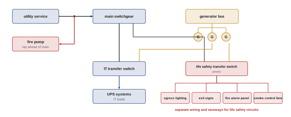
Life safety systems must keep working during a fire, which often involves a loss of normal power. These loads include emergency lighting, exit signs, the fire alarm system, fire pumps, smoke control fans, elevators used for firefighting or accessible evacuation, and in some buildings voice communication systems. Codes require them to be supplied from an emergency power source that starts and transfers automatically within a short time, and to be kept separate from other wiring so that a fault in the normal or IT systems does not take them out.
In the US, the IBC requires emergency illumination of the means of egress, averaging at least 1 footcandle (about 11 lx) with a minimum of 0.1 footcandle at floor level, for at least 90 minutes. The NEC distinguishes emergency systems (Article 700), which must restore power within 10 seconds and supply egress lighting, exit signs and similar loads; legally required standby systems (Article 701), within 60 seconds; and optional standby systems (Article 702), which include the generators serving IT loads. Emergency generators are installed to NFPA 110, and fire pump power follows NEC Article 695.
In a data center, the large generators that back up the IT load are usually treated as optional standby for code purposes. Life safety loads are normally served by a separate emergency branch with its own automatic transfer switch, which may draw from the same generator plant but has priority over IT loads and is wired separately in its own raceways. Some designs use a dedicated smaller life safety generator or battery inverter instead. Keeping these systems separate ensures that maintenance on the IT power system, or a fault in it, does not leave the egress routes dark.
Worked problem
Emergency lighting battery
An emergency lighting unit supplies four 9 W LED heads at 24 V for a required duration of 90 minutes. The battery should not be discharged below 80 percent of its capacity at end of life, and capacity may fall to 80 percent of nameplate as it ages. What nameplate battery capacity is needed?
Show solution
- Current: \(4 \times 9 / 24 = 1.5\) A.
- Energy for the duration: \(1.5 \times 1.5 = 2.25\) Ah.
- Allowing 80 percent usable depth and 80 percent end-of-life capacity: \(2.25 / (0.8 \times 0.8) = 3.5\) Ah.
Answer: About 3.5 Ah at 24 V, so a standard 24 V unit of at least 3.5 Ah, and in practice the next size up. Units must be tested monthly for function and annually for the full 90 minutes, as required by NFPA 101 and the fire code.
Electrical rooms and transformers
Electrical rooms concentrate the equipment most likely to start a fire, so their design follows the compartmentation principles of Lesson 1: rated separations from data halls, fire-stopped penetrations, detection inside the room, and suppression appropriate to the equipment. Ventilation and cooling keep equipment within its temperature rating, because heat shortens the life of insulation and electronics. Access should be restricted to qualified people.
Transformers filled with mineral oil hold a large quantity of flammable liquid, and a transformer failure can cause a pool fire. Options to reduce the hazard include dry-type transformers indoors, liquid-filled transformers using less-flammable fluids such as natural esters (vegetable-based oils with high fire points), and locating oil-filled units outdoors with spacing from buildings, containment curbs and fire barriers where spacing is not possible.
Indoor installations of oil-filled transformers require fire-rated vaults under NEC Article 450, and insurers such as FM Global publish spacing tables for outdoor transformers based on liquid volume and type.
Common mistakes
MistakeAccepting a small thermographic temperature rise measured at light load.
InsteadCorrect readings to full load; temperature rise scales roughly with current squared.
MistakeAssuming the utility main breaker de-energizes the whole facility.
InsteadIdentify UPS, battery and generator sources and isolate each one.
MistakeRelying on PPE alone to manage arc flash.
InsteadWork de-energized where possible and reduce clearing time with engineering controls.
MistakeFeeding egress lighting from the IT UPS distribution.
InsteadProvide a separate emergency branch with priority and separate wiring.
MistakePlacing oil-filled transformers next to buildings without separation.
InsteadUse spacing, barriers, less-flammable fluids or dry-type units.
Summary and key terms
- Electrical faults are the main ignition source in data centers; connection heating follows P = I²R.
- Thermography, continuous temperature monitoring and torque checks find faults before they burn.
- Thermographic readings must be corrected for load and interpreted against similar components.
- Arc flash incident energy depends strongly on clearing time and working distance; the boundary is at 1.2 cal/cm².
- NFPA 70E governs electrical work safety; IEEE 1584 provides the calculation.
- Maintenance switching, zone-selective interlocking and arc flash relays reduce incident energy.
- Life safety loads need an emergency source with fast transfer and separate wiring from IT power.
- High-resistance connection
- A joint whose resistance has risen, causing local heating.
- Infrared thermography
- Imaging of surface temperatures with a thermal camera.
- Emissivity
- How effectively a surface emits infrared radiation compared with an ideal emitter.
- Arc flash
- A release of energy from an electric arc causing heat, light and pressure.
- Incident energy
- Thermal energy per unit area at a working distance, in cal/cm².
- Arc flash boundary
- The distance at which incident energy falls to 1.2 cal/cm².
- Zone-selective interlocking
- Communication between breakers that removes intentional delay for faults in their zone.
- Energy-reducing maintenance switching
- Temporarily faster protection settings while work is done.
- Emergency system
- A power system that supplies life safety loads within seconds of a failure.
- Natural ester fluid
- A vegetable-based transformer liquid with a high fire point.
Practice problems
Work each problem on paper first, then reveal the answer to check.
A lug carries 400 A with a resistance of 200 micro-ohms. How much heat does it dissipate?
Show answer
400² × 200 × 10⁻⁶ = 32 W.
A connection is 5 °C hotter than similar ones at 50% load. Estimated rise at full load?
Show answer
5 / 0.25 = 20 °C, a major deficiency.
Why are shiny copper surfaces hard to measure with a thermal camera?
Show answer
Their low emissivity makes them reflect radiation and appear cooler.
What is the significance of 1.2 cal/cm²?
Show answer
It is the onset of a second-degree burn and defines the arc flash boundary.
If clearing time halves, how does incident energy change (approximately)?
Show answer
It roughly halves.
Name two ways to reduce arc flash clearing time.
Show answer
Maintenance switching, zone-selective interlocking, arc flash relays, differential protection.
Why does opening the utility main not make a data center safe for firefighters?
Show answer
UPS batteries and generators continue to supply power.
What average illuminance does the IBC require for egress emergency lighting?
Show answer
1 footcandle average, 0.1 footcandle minimum.
Six 6 W heads at 12 V for 1 hour, with 0.8 × 0.8 derating. Battery capacity?
Show answer
3 A × 1 h / 0.64 = 4.7 Ah.
Give two ways to reduce the fire hazard of transformers.
Show answer
Dry-type units, natural ester fluids, outdoor location with spacing, barriers and containment.
Lesson quiz · 5 questions
Score 60% or more to complete this lesson.
Create a free account to save your progress, take quizzes and earn a certificate.