
DCE-440 · Lesson 6 of 12 · 35 min
Sprinkler hydraulics, water supplies and fire pumps
Lesson 5 explained why most data centers still rely on sprinklers, and how pre-action systems keep their pipes dry until a fire is confirmed. A sprinkler system only works, however, if enough water reaches the heads that open, at enough pressure, for as long as the fire burns. Making sure of this is the job of the hydraulic calculation, which traces water from the most remote sprinkler back through the pipes to the water supply, and compares the flow and pressure needed with what the supply can deliver. Where the supply falls short, a fire pump or a storage tank makes up the difference. This lesson works through the design approach, the equations for sprinkler discharge and pipe friction, a calculation for a pre-action system, the testing and representation of water supplies, the selection of fire pumps, and the details of sprinkler layout that matter in data halls.
The design approach
Sprinkler systems are designed to NFPA 13, using a density and area approach. The hazard classification sets a design density (the minimum discharge per unit floor area) and a design area (the area over which all sprinklers are assumed to open at once). The design area is placed in the hydraulically most demanding part of the system, usually the part farthest from the water supply, and every sprinkler within it must discharge at least the design density over its coverage area.
For a data hall designed to Ordinary Hazard Group 1 criteria, the design is 0.15 gpm/ft² over 1,500 ft², with a hose stream allowance of 250 gpm and a water supply duration of 60 to 90 minutes. Insurers may require higher densities or larger areas, especially where cables and plastics are dense.
The design area is a rectangle whose long side runs parallel to the branch lines (the smallest pipes, to which the sprinklers are attached), with a length of at least 1.2 times the square root of the design area. This shape includes several heads on each of a few branch lines, which is more demanding than a square, because water must travel along the full length of each line.
Worked problem
Sprinklers in the design area
Sprinklers are spaced 12 ft apart along branch lines, with branch lines 11 ft apart, so each covers 132 ft². How many sprinklers are in a 1,500 ft² design area, and how are they arranged?
Show solution
- Number of heads: \(1500 / 132 = 11.4\), rounded up to 12.
- Length parallel to the branch lines: \(1.2\sqrt{1500} = 46.5\) ft, which needs \(46.5 / 12 = 3.9\), so 4 heads per line.
- Branch lines: \(12 / 4 = 3\) lines.
Answer: Twelve sprinklers, arranged as 4 heads on each of 3 branch lines at the far end of the system. The hydraulic calculation assumes all 12 open together.
Sprinkler discharge
The flow from a sprinkler depends on the pressure at its inlet and on its orifice size, expressed as a K-factor:
where \(q\) is the flow in gpm and \(p\) the pressure in psi. The most common standard-orifice sprinkler has \(K = 5.6\), and larger orifices (K8.0, K11.2 and above) deliver more water at the same pressure. NFPA 13 sets a minimum operating pressure of 7 psi at any sprinkler.
Worked problem
The most remote sprinkler
Each sprinkler covers 132 ft² and the design density is 0.15 gpm/ft². What flow and pressure are needed at the most remote K5.6 sprinkler?
Show solution
- Minimum flow: \(0.15 \times 132 = 19.8\) gpm.
- Pressure: \(p = (q/K)^2 = (19.8/5.6)^2 = 12.5\) psi, which exceeds the 7 psi minimum.
Answer: About 19.8 gpm at 12.5 psi. Every other sprinkler in the design area will receive more pressure and therefore discharge more, because it is closer to the supply.
Friction loss in pipes
Water loses pressure through friction as it flows along pipes and through fittings, and gains or loses pressure with changes in elevation. NFPA 13 uses the Hazen-Williams formula for friction loss:
where \(p_f\) is the friction loss in psi per foot of pipe, \(Q\) the flow in gpm, \(d\) the actual internal diameter in inches, and \(C\) the roughness coefficient. Elevation changes add or subtract about 0.433 psi per foot.
The C factor depends on the pipe material and the system type. NFPA 13 assigns black steel pipe a C of 120 in wet systems but 100 in dry-pipe and pre-action systems, because pipes that alternate between wet and dry corrode faster and become rougher; copper and listed plastic pipe use 150. Nitrogen inerting, described in Lesson 5, slows this corrosion. Fittings such as elbows and tees are included by adding an equivalent length of straight pipe for each one.
The strong dependence on diameter (to the power 4.87) means that a modest increase in pipe size greatly reduces friction loss. Doubling the flow multiplies the loss by about 3.6, while increasing the diameter by 20 percent cuts it by more than half. Pipe sizing is therefore a trade-off between pipe cost and the pressure the water supply must provide.
Calculating a pre-action system
A hydraulic calculation starts at the most remote sprinkler with its minimum flow and pressure, then works back toward the supply. At each step, the friction loss in the pipe segment is added to find the pressure at the next sprinkler, that sprinkler's flow is calculated from its K-factor, and the flows are added. Where a branch line joins the cross main, the whole line can be treated as an equivalent sprinkler with its own K-factor, so identical lines can be calculated quickly. Finally, losses in the feed main, riser and valves and the elevation of the sprinklers above the supply are added.
import math

# Hydraulic calculation of a pre-action sprinkler design area (SI units, NFPA 13 method)
def friction(Q, d, C=100):
    # Hazen-Williams, bar per metre, Q in L/min, internal diameter d in mm
    return 6.05e5 * Q ** 1.85 / (C ** 1.85 * d ** 4.87)

K = 80.0                       # sprinkler K-factor, L/min per bar^0.5
density, area_per_head = 6.1, 12.0          # mm/min and m2 per head
q_min = density * area_per_head             # minimum flow from the end head, L/min
p = max((q_min / K) ** 2, 0.5)              # pressure at the end head, at least 0.5 bar
q = K * math.sqrt(p)
print(f"end head: {q:.1f} L/min at {p:.3f} bar")

# Branch line: 4 heads 3.6 m apart, then a 2 m drop (with fittings) to the cross main
segments = [(3.6, 27.9), (3.6, 27.9), (3.6, 36.6), (2.0 + 2.4, 36.6)]   # length incl. fitting equivalents, ID mm
Q = q
for i, (L, d) in enumerate(segments, start=1):
    p += friction(Q, d) * L
    if i < 4:                   # another head at the downstream end of this segment
        qh = K * math.sqrt(p)
        Q += qh
        print(f"head {i + 1}: {qh:.1f} L/min at {p:.3f} bar, line flow {Q:.1f} L/min")
p += 0.098 * 0.6               # cross main 0.6 m below the branch lines
Kline = Q / math.sqrt(p)
print(f"branch line 1 at cross main: {Q:.0f} L/min at {p:.2f} bar (line K = {Kline:.1f})")

# Cross main (65 mm, ID 66.9 mm) feeding 3 identical branch lines 3.3 m apart
Qtot = Q
for n in (2, 3):
    p += friction(Qtot, 66.9) * 3.3
    Qn = Kline * math.sqrt(p)
    Qtot += Qn
    print(f"branch line {n}: {Qn:.0f} L/min at {p:.2f} bar; total {Qtot:.0f} L/min")

# Feed main to the riser (100 mm, ID 108.2 mm, 60 m incl. fittings) and 6 m rise to the ceiling
p += friction(Qtot, 108.2) * 60 + 0.098 * 6.0
p += 0.35                      # pre-action valve and riser losses (from the valve data sheet)
hose = 950                     # hose stream allowance, L/min
print(f"sprinkler demand at the base of the riser: {Qtot:.0f} L/min at {p:.2f} bar")
print(f"with hose allowance: {Qtot + hose:.0f} L/min; nominal minimum {density * 139:.0f} L/min")end head: 73.2 L/min at 0.837 bar head 2: 77.9 L/min at 0.949 bar, line flow 151.1 L/min head 3: 93.8 L/min at 1.375 bar, line flow 244.9 L/min head 4: 102.8 L/min at 1.653 bar, line flow 347.8 L/min branch line 1 at cross main: 348 L/min at 2.36 bar (line K = 226.3) branch line 2: 350 L/min at 2.39 bar; total 697 L/min branch line 3: 356 L/min at 2.48 bar; total 1054 L/min sprinkler demand at the base of the riser: 1054 L/min at 3.77 bar with hose allowance: 2004 L/min; nominal minimum 848 L/min
The calculation shows several features of real systems. The sprinkler nearest the cross main on each line discharges about 40 percent more than the most remote one, and the total sprinkler flow of about 1,050 L/min is roughly a quarter higher than the nominal 848 L/min (6.1 mm/min over 139 m²). This overdischarge is unavoidable in a tree system, in which water reaches each head by only one path. Gridded systems, in which branch lines connect to mains at both ends, balance pressures better and are common in wet systems, but they are harder to fill and drain and so are rarely used for pre-action systems. Most of the pressure is lost in the small pipes at the end of each branch line, and upsizing them would reduce the demand.
In practice, hydraulic calculations are done with specialized software that handles hundreds of pipes, loops and fittings. The engineer's job is to check that the software's inputs (pipe sizes, lengths, fittings, C factors, K-factors and the location of the design area) are correct and the results plausible.
Water supplies
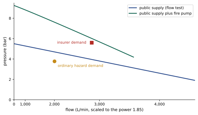
A sprinkler system can be fed from a public water main, from a private tank or reservoir with a pump, or from both. The capacity of a public main is determined by a flow test: the static pressure is measured with no flow, then a hydrant is opened and the flow and the residual pressure are recorded. Because friction loss varies with flow to the power 1.85, the pressure available at any other flow can be estimated as:
where \(P_s\) is the static pressure, \(P_r\) the residual pressure measured at the test flow \(Q_t\). Plotted on graph paper whose horizontal axis is scaled to \(Q^{1.85}\), this supply curve is a straight line, and the system demand (sprinkler flow plus hose allowance, at the required pressure) is plotted on the same graph. The supply is adequate if the demand point lies below the supply curve, usually with a safety margin required by the authority or insurer. Pressure in public mains varies with daily demand, seasons and future development, so tests should be recent and taken at times of high demand where possible.
Private fire water storage is common at data centers, either because the public supply is inadequate or because the owner wants independence from it. Tanks are sized for the total demand multiplied by the required duration, plus allowances, and are designed and maintained to NFPA 22. Site fire mains, hydrants and their connection to the public system were covered in DCE-430, Lesson 2.
Worked problem
Sizing a fire water tank
A data center's largest fire demand is 530 gpm (sprinklers plus hose) for 90 minutes. What tank volume is needed if the owner adds 10 percent for unusable volume?
Show solution
- Required volume: \(530 \times 90 = 47{,}700\) gal.
- With 10 percent added: \(52{,}500\) gal.
Answer: About 52,500 gal. A refill connection, level monitoring and protection against freezing are also needed, and the tank must be inspected and tested regularly.
Fire pumps
Where the supply cannot deliver the required pressure, a fire pump boosts it. Fire pumps are designed and installed to NFPA 20. Most are horizontal split-case or vertical inline centrifugal pumps driven by an electric motor or a diesel engine, and each is rated at a specific flow and net pressure. NFPA 20 requires that a listed fire pump deliver at least 65 percent of its rated pressure at 150 percent of its rated flow, and that its pressure with no flow (churn) not exceed 140 percent of rated pressure. These limits ensure the pump keeps delivering useful pressure if demand exceeds the design, without generating dangerously high pressure at low flow.
# Water supply check and fire pump selection
Ps, Pr, Qt = 5.5, 3.8, 3000.0      # flow test: static and residual pressure (bar) at test flow (L/min)

def city(Q):
    # supply curve from the flow test (pressure falls with flow to the power 1.85)
    return Ps - (Ps - Pr) * (Q / Qt) ** 1.85

def service_loss(Q):
    # underground main and backflow preventer: 0.5 bar at 2,000 L/min, scaled by flow
    return 0.5 * (Q / 2000.0) ** 1.85

def check(name, q_spr, p_req, hose=950.0, margin=0.35):
    available = city(q_spr + hose) - service_loss(q_spr)
    status = "OK" if available >= p_req + margin else "NOT ENOUGH"
    print(f"{name}: need {p_req:.2f} bar at {q_spr:.0f} L/min (+{hose:.0f} hose); "
          f"available {available:.2f} bar; {status}")
    return available

# Case 1: the design calculated in the previous example
check("Ordinary Hazard 1 design", 1054, 3.77)
# Case 2: an insurer asks for a higher density over a larger area
need_p, need_q = 5.6, 1900
avail = check("Insurer design", need_q, need_p)

# Fire pump rated 1,900 L/min at 3.0 bar net pressure; curve meets NFPA 20 limits
Qr, Pnet = 1900.0, 3.0
def pump(Q):
    return Pnet * (1.25 - 0.25 * (Q / Qr) ** 2)
print(f"pump churn {pump(0):.2f} bar ({pump(0) / Pnet:.0%} of rated, limit 140%)")
print(f"pump at 150% flow {pump(1.5 * Qr):.2f} bar ({pump(1.5 * Qr) / Pnet:.0%} of rated, minimum 65%)")
for Q in (1000, 1900, 2850):
    suction = city(Q + 950) - service_loss(Q)
    print(f"flow {Q:4.0f} L/min: suction {suction:.2f} bar + pump {pump(Q):.2f} = {suction + pump(Q):.2f} bar"
f"; public main {city(Q + 950):.2f} bar")Ordinary Hazard 1 design: need 3.77 bar at 1054 L/min (+950 hose); available 4.54 bar; OK Insurer design: need 5.60 bar at 1900 L/min (+950 hose); available 3.50 bar; NOT ENOUGH pump churn 3.75 bar (125% of rated, limit 140%) pump at 150% flow 2.06 bar (69% of rated, minimum 65%) flow 1000 L/min: suction 4.60 bar + pump 3.54 = 8.14 bar; public main 4.73 bar flow 1900 L/min: suction 3.50 bar + pump 3.00 = 6.50 bar; public main 3.95 bar flow 2850 L/min: suction 1.90 bar + pump 2.06 = 3.97 bar; public main 2.87 bar
In the first case the public supply alone meets the ordinary hazard design with margin. In the second, an insurer's higher design needs 5.6 bar, but the supply offers only 3.5 bar at that flow, so a pump is required. A pump rated at 1,900 L/min and 3.0 bar raises the discharge pressure to 6.5 bar at the design flow, meeting the demand with margin. The calculation should also check that the pressure at churn plus the maximum static supply pressure does not exceed the rating of the system components (commonly 12 bar, or 175 psi), and that drawing the pump's full flow does not reduce the pressure in the public main below the minimum the water utility allows.
Fire pump installations include several features that set them apart from ordinary pumps:
- Reliable power: an electric fire pump is fed by a dedicated connection that is not interrupted by the building's main disconnect, often with a standby generator or a second utility source, and the motor is protected so that it runs to destruction rather than tripping on overload during a fire. Diesel pumps have their own fuel supply and batteries.
- A jockey pump: a small pump that maintains pressure in the system against minor leakage, so the main pump starts only on a real demand.
- A controller that starts the pump automatically when system pressure falls, and that must be stopped manually.
- A protected pump room, with heating, drainage and separation from the rest of the building.
- A test header or flow meter so the pump can be flow-tested annually without wasting water unnecessarily.
Standpipes and hose connections
Firefighters need water inside large buildings without dragging hose from the street. Standpipe systems, required by the IBC in many buildings and designed to NFPA 14, provide hose connections in exit stairs and other locations, supplied by the building's water system and by a fire department connection outside, through which fire department pumpers can boost pressure and flow. The fire department connection is also usually connected to the sprinkler system, so the fire department can supplement its supply.
The location of standpipe connections in a data center should be agreed with the fire department as part of the pre-incident plan, because hose lines laid through security doors and mantraps can be difficult, and the fire department will want to know where water use would cause the least harm.
Sprinkler layout in data halls
Data halls create layout challenges that general offices do not:
- Obstructions: cable trays, busways, ducts and containment roofs block water from reaching the floor. NFPA 13 requires sprinklers below obstructions wider than 1.2 m (4 ft), and has rules for the distance between sprinklers and narrower obstructions.
- Containment: hot-aisle and cold-aisle containment roofs can prevent water from reaching a fire inside the contained space. Options include sprinklers within each contained aisle, or containment panels that are listed to shrink or drop away when heated, before the sprinklers above operate.
- Water delivery time: in pre-action and dry systems, water must reach the most remote sprinkler within a time set by NFPA 13 according to the hazard (for example, 50 seconds for ordinary hazard), which limits system size and may require more risers or smaller systems.
- Leaks and drainage: pre-action pipes must be pitched so that condensation and test water drain to low points, and drains and inspector's test connections located away from equipment. Leak detection under raised floors and drip trays under valves reduce the consequences of leaks.
- Sprinkler temperature rating: hot aisles may run at 40 °C or more, so sprinklers in or above them may need intermediate temperature ratings (about 79 to 107 °C) to avoid unwanted operation, and the effect on response time must be considered.
These details are best resolved through coordination drawings and three-dimensional models that show sprinklers, trays, busways, lights and containment together, because a sprinkler placed on paper can easily end up behind a cable tray once construction begins.
Common mistakes
MistakeUsing the wet-system C factor of 120 for pre-action piping.
InsteadUse C = 100 for black steel in dry-pipe and pre-action systems unless the standard allows otherwise.
MistakeCalculating only the nominal density times the design area.
InsteadCalculate from the most remote head; overdischarge raises the actual demand.
MistakeRelying on an old or off-peak water flow test.
InsteadUse a recent test, at times of high demand, with a safety margin.
MistakeIgnoring churn pressure when adding a fire pump.
InsteadCheck that churn plus maximum static pressure stays within component ratings.
MistakePlacing sprinklers without considering cable trays and containment.
InsteadCoordinate in 3D and add sprinklers below wide obstructions and inside containment.
Summary and key terms
- Sprinkler design uses a density over a design area in the hydraulically most demanding location.
- The design area is a rectangle with length 1.2√A along the branch lines.
- Sprinkler flow is q = K√p, with a minimum pressure at the most remote head.
- Hazen-Williams friction loss depends on flow to the 1.85 power and diameter to the 4.87 power; C = 100 for pre-action black steel.
- Calculations work back from the most remote head; tree systems overdischarge near the supply.
- Water supplies are characterized by flow tests; demand plus hose must lie below the supply curve with margin.
- Fire pumps must give 65% of rated pressure at 150% flow, with churn at most 140%; layout must address obstructions, containment and water delivery time.
- Design density
- The minimum water discharge per unit floor area.
- Design area
- The area over which all sprinklers are assumed to operate.
- Branch line
- A small pipe to which sprinklers are directly attached.
- K-factor
- The constant relating sprinkler flow to the square root of pressure.
- Hazen-Williams formula
- An empirical equation for friction loss in water pipes.
- C factor
- The roughness coefficient in the Hazen-Williams formula.
- Overdischarge
- Flow above the minimum from sprinklers closer to the supply.
- Flow test
- Measurement of static and residual pressure at a known flow from a water main.
- Churn pressure
- The pressure a fire pump produces at zero flow.
- Jockey pump
- A small pump that maintains system pressure against minor leakage.
Practice problems
Work each problem on paper first, then reveal the answer to check.
How long must the design area be along the branch lines for 2,500 ft²?
Show answer
1.2√2500 = 60 ft.
A K5.6 sprinkler operates at 16 psi. What is its flow?
Show answer
5.6 × 4 = 22.4 gpm.
Density 0.2 gpm/ft², 100 ft² per head, K5.6. Minimum pressure at the end head?
Show answer
q = 20 gpm; p = (20/5.6)² = 12.8 psi.
By what factor does friction loss rise when flow doubles?
Show answer
\(2^{1.85} \approx 3.6\).
Why do pre-action systems use a lower C factor?
Show answer
Alternating wet and dry conditions increase corrosion and roughness.
Why does a tree system overdischarge?
Show answer
Heads closer to the supply receive higher pressure and discharge more than the minimum.
Static 72 psi, residual 50 psi at 660 gpm. Pressure available at 530 gpm?
Show answer
72 − 22 × 0.803^1.85 = 72 − 14.6 = 57.4 psi.
A pump is rated at 4 bar. What are its maximum churn and minimum 150% flow pressures?
Show answer
5.6 bar and 2.6 bar.
What is the purpose of a jockey pump?
Show answer
To maintain system pressure against small leaks so the main pump starts only on demand.
What NFPA 13 rule applies to cable trays wider than 1.2 m?
Show answer
Sprinklers are required beneath them.
Lesson quiz · 5 questions
Score 60% or more to complete this lesson.
Create a free account to save your progress, take quizzes and earn a certificate.