
CON-315 · Lesson 12 of 12 · 22 min
Capstone: a field engineering plan for an invented project
The previous lessons covered the parts of field engineering one at a time: drawings and questions, control, layout by phase, tolerances, embeds, constructability, sequencing, measurement and records. On a real project they happen together, and the field engineer must plan them as one system. This capstone brings the course together as a field engineering plan for Larkspur Commons, prepared by Mei at the start of construction and updated as the project proceeds. The plan is a working document, typically ten to twenty pages, that tells the site team, the trades and the design team how layout, checking and records will be managed. The structure below can be adapted to any building project.
1. Project summary and scope of field engineering
Larkspur Commons is an invented six-story rental building in Boise, Idaho: 112 homes over shops, with a two-story concrete podium and a partial underground parking level, a post-tensioned transfer slab at level 3 and four stories of light wood frame above. The building grid has gridlines 1 to 9 and A to F at 25'-7". Thornbury Builders is the general contractor as construction manager at risk.
The plan first defines who does what. The owner's surveyor provides primary control and the licensed surveys of the building on its lot. Thornbury's field engineers provide secondary control, layout for all self-performed work and for gridlines and offset lines used by subcontractors, independent checks, embed coordination, surveys and scans of completed work, and the as-built record. Subcontractors lay out their own work from Thornbury's offset lines and are responsible for its accuracy; the shoring and post-tensioning subcontractors do their own specialist layout, which Thornbury checks at key points.
| Responsibility | Owner's surveyor | Thornbury field engineering | Subcontractors |
|---|---|---|---|
| Property lines and primary control | Provides | Protects and checks | Uses |
| Secondary control and gridlines | Provides | Uses | |
| Layout of self-performed concrete work | Provides and checks | ||
| Layout of trade work | Checks critical items | Provides from offset lines | |
| Embed coordination | Leads | Supply, place and confirm | |
| Licensed location surveys | Provides | Arranges | |
| As-built record | Lot survey | Compiles and verifies | Provides redlines |
2. Documents and questions
The plan sets the rules for working documents: a single current set on site and on the field platform, posting of every answered question and change within two working days, weekly collection of trade redlines and a drawing register checked before every layout session (lesson 2). It sets a target turnaround for questions agreed with the design team and a rule that every question includes a location, references, a proposed solution and a needed-by date tied to the look-ahead schedule. It names Arjun as owner of the question log, with Mei reviewing every question before it is sent.
3. Control and coordinate systems
The control section of the plan records the coordinate system and datum: ground-scaled project coordinates based on state plane coordinates on NAD 83 in international feet, as the surveyor specified, and elevations on NAVD 88, with the relationship between project elevations and relative floor elevations stated clearly. It lists the four primary control points and two benchmarks, the planned secondary control on each slab, the plumbing openings for control transfer, and the tolerances for control checks. Control is checked every Monday and before any critical layout, and any point that fails a check is marked disturbed until re-established (lesson 3).
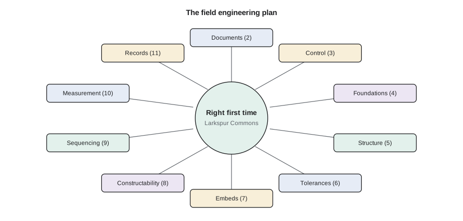
4. Layout by phase
For each phase, the plan lists what will be laid out, by whom, from which control, with what instruments and with what check. It identifies the critical items that follow the two-person rule.
| Phase | Main layout items | Critical items checked independently |
|---|---|---|
| Excavation and shoring | Top of cut, shoring line, bottom of excavation | Shoring line along the north property line |
| Foundations | Footings, walls, dowels, underslab services | Footing positions, anchor bolts, elevator pit |
| Podium structure | Columns, walls, core, deck edges, openings, embeds | Columns, core and shaft, slab edges, cladding anchors, transfer slab embeds |
| Wood frame | Wall lines, shear walls, openings, hold-down positions | Shear walls and hold-downs, stacked bearing walls, elevator interface |
| Envelope | Window rough openings, cladding lines, flashings | Window openings before delivery, cladding brackets |
| Interiors | Partitions, bulkhead zones, service positions | Corridor bulkheads, stair and elevator interfaces |
5. Tolerances and interfaces
The plan lists the tolerances that apply to each system, from the specification and the referenced standards, and identifies the interfaces where tolerance compatibility must be checked before fabrication: slab edges and cladding, the elevator shaft and rails, floor-to-floor heights and the steel stairs, wall lines and prefabricated wall panels, and floor flatness and finishes. For each, it states when the as-built condition will be measured and who receives the results (lessons 6 and 8). The plan also records the decisions already made, such as the tighter slab edge tolerance at the cladding zones agreed after the tolerance stack analysis in lesson 6.
6. Embeds and openings
Every pour has an embed register, opened when the pour is scheduled in the look-ahead and closed when the pour card is signed. Sleeve coordination against structure and tendons is completed two weeks before each pour, with a model clash review and a rule-based check; the embed walk with the trades happens the day before the pour (lesson 7). The plan sets the coring and drilling permit procedure for the post-tensioned transfer slab and the opening protection rules.
7. Constructability and prefabrication
The plan schedules constructability reviews before each major phase with the relevant trades, using the checklist from lesson 8, and lists the prefabricated elements that need as-built measurement before release for fabrication: wall panels, roof trusses, steel stairs, cladding brackets and elevator rails. It also records lessons learned as they arise.
8. Sequencing and hold points
The plan identifies the hold points where work must not proceed until field engineering checks are complete: before each pour, before stressing the transfer slab, before framing starts on the podium, before closing walls on each floor and before releasing prefabricated elements. Each hold point has a checklist and a named person who signs it off. The plan also notes the technical sequencing decisions already made, such as splitting the transfer slab into two pours with a planned construction joint and a standby pump (lesson 9).
9. Measurement, scanning and monitoring
Measurement in the plan is driven by purpose. Columns, slab edges and the core are surveyed or scanned within three working days of stripping. Shoring and the neighboring building are monitored to the shoring engineer's schedule and trigger levels. Walls and ceilings are captured with 360-degree photos before closing, and complex areas are scanned. Progress quantities for the main trades are measured monthly (lesson 10).
10. Records and handover
The records section names the records, their owners and their formats: control sheet, layout log, embed registers, question log, deviation register, survey files, scan and photo archive, redlines and the record set. It sets the target of keeping the record set current within two weeks throughout the project, tracks progress monthly in the last six months, and lists the handover items, including the control information (lesson 11).
11. Resources
A plan is only as good as the people available to carry it out. Field engineering demand rises and falls with the work, and the busiest periods often overlap, for example when the last podium slabs, the first wood-frame floors and the start of prefabrication happen in the same month. Mei estimates the weekly hours for each activity during the transition from podium to wood frame and compares them with the capacity of two field engineers.
# Field engineering capacity plan for the busiest months (invented estimates)
weeks = ["Wk 1", "Wk 2", "Wk 3", "Wk 4", "Wk 5", "Wk 6", "Wk 7", "Wk 8"]
demand = {  # hours per week by activity
    "Podium layout and checks": [42, 40, 44, 36, 12, 0, 0, 0],
    "Embed coordination and walks": [14, 16, 18, 12, 6, 0, 0, 0],
    "Wood-frame wall lines": [0, 0, 0, 10, 24, 28, 28, 28],
    "Surveys and scans": [8, 10, 8, 12, 10, 8, 8, 10],
    "Questions, drawings, records": [22, 22, 24, 24, 22, 22, 20, 20],
    "Prefabrication checks": [0, 0, 4, 8, 10, 10, 8, 8],
}
capacity = 2 * 47        # two field engineers, about 47 productive hours each per week
print("Week   demand  capacity  gap")
for i, w in enumerate(weeks):
    d = sum(v[i] for v in demand.values())
    gap = d - capacity
    print(f"{w:5s} {d:7d} {capacity:9d} {gap:+5d}{'  <- add help or move work' if gap > 0 else ''}")
peak = max(range(len(weeks)), key=lambda i: sum(v[i] for v in demand.values()))
print(f"Peak in {weeks[peak]}: plan a layout subcontractor or a third person for weeks with a positive gap")Week demand capacity gap Wk 1 86 94 -8 Wk 2 88 94 -6 Wk 3 98 94 +4 <- add help or move work Wk 4 102 94 +8 <- add help or move work Wk 5 84 94 -10 Wk 6 68 94 -26 Wk 7 64 94 -30 Wk 8 66 94 -28 Peak in Wk 4: plan a layout subcontractor or a third person for weeks with a positive gap
Demand exceeds capacity in weeks 3 and 4, when the last podium layout overlaps the start of wood-frame layout and prefabrication checks. Rather than let checking suffer, which is what usually happens when field engineers are overloaded, Mei proposes engaging a layout subcontractor for those two weeks to lay out the wood-frame wall lines on level 3 under her checking. Dana agrees, because a missed check during that period would cost far more than a few days of layout help.
12. Measuring how the plan works
The plan includes a small set of indicators reviewed monthly with Dana and Priya. They focus on outcomes, such as errors reaching the work, rather than activity, such as the number of points set.
# Field engineering performance indicators for the podium (invented records)
layout_items = 1840           # items laid out (points, lines, embeds)
errors_found_by_check = 23    # errors caught by independent checks before work was built
errors_found_after = 3        # errors found after the work was built
rfis = 96; rfis_late = 11     # questions sent; answers received after the needed-by date
pours = 14; pours_delayed = 1 # pours delayed by an incomplete field engineering check
scans = 9; scans_within_3_days = 7
print(f"Errors caught before building: {errors_found_by_check / (errors_found_by_check + errors_found_after):.0%}")
print(f"Errors reaching the work: {errors_found_after / layout_items * 1000:.1f} per 1,000 items")
print(f"Questions answered late: {rfis_late / rfis:.0%}")
print(f"Pours delayed by field engineering: {pours_delayed} of {pours}")
print(f"Scans processed within 3 days of capture: {scans_within_3_days / scans:.0%}")Errors caught before building: 88% Errors reaching the work: 1.6 per 1,000 items Questions answered late: 11% Pours delayed by field engineering: 1 of 14 Scans processed within 3 days of capture: 78%
Independent checks caught 88 % of the layout errors made during the podium phase, and three errors reached the work out of 1,840 items laid out. Each of those three was investigated: one came from a superseded sheet, one from a misread dimension and one from a disturbed control point used before the Monday check. The fixes, a stricter drawing register check, a second reading of every critical dimension and a mid-week control check during heavy excavation, went into the plan. About one in nine questions was answered after its needed-by date, which Priya raises with the architect. One pour was delayed by an incomplete check, and two scans were processed late, so Mei adjusts the scanning schedule for the wood-frame floors.
Indicators like these must be used carefully. If people are judged on the number of errors found, they may stop reporting; if they are judged on speed, they may skip checks. The purpose is to improve the system, in the spirit of CON-410 and CON-305, not to blame individuals.
Putting the plan to work
A field engineering plan is useful only if it shapes daily decisions. On Larkspur Commons, the plan is reviewed with the superintendent at the start of each phase, shared with subcontractor foremen at their start-up meetings, and updated whenever a lesson is learned. Its checklists are used at every pour and every hold point. When a new field engineer joins the team, the plan is the first document he or she reads.
The deeper message of this course is that field engineering is a discipline of prevention. Its successes are invisible: the anchor bolts that fit, the cladding that hangs without modification, the sleeve that was moved before the pour, the record that lets a future contractor core a slab safely. The best field engineers are the ones whose projects seem to have no layout problems at all, because they found them all on paper, in the forms or in the survey, at the cheapest possible moment.
Common mistakes
MistakeWriting a field engineering plan and then filing it away.
InsteadUse the plan's checklists at every hold point and update it as lessons are learned.
MistakeLetting checks slip when field engineers are overloaded.
InsteadPlan capacity against demand and add help for peaks so that checking is protected.
MistakeMeasuring field engineering by activity alone.
InsteadTrack outcomes such as errors reaching the work, late answers and delayed pours.
MistakeUsing indicators to blame individuals.
InsteadUse them to find and fix system causes.
MistakeLeaving responsibilities between surveyor, contractor and trades unstated.
InsteadDefine them in a responsibility matrix at the start of the project.
Summary and key terms
- A field engineering plan ties documents, control, layout, tolerances, embeds, constructability, sequencing, measurement and records into one system.
- A responsibility matrix defines what the surveyor, the contractor and each trade provide and check.
- Each phase lists its layout items and the critical items that follow the two-person rule.
- Interfaces needing tolerance compatibility checks and as-built measurement before fabrication are identified early.
- Hold points with checklists and named sign-offs protect pours, stressing, framing, closing walls and fabrication.
- Capacity planning keeps checking from being squeezed out during peaks.
- Outcome indicators show how well the system works and guide improvements, not blame.
- Field engineering succeeds by preventing problems at the cheapest possible moment.
- Field engineering plan
- A working document that sets out how layout, checking, coordination, measurement and records will be managed on a project.
- Responsibility matrix
- A table showing who provides, checks and uses each field engineering item.
- Hold point
- A stage at which work must not proceed until specified checks are complete and signed off.
- Critical item
- An element whose position or condition has high consequences if wrong, requiring independent checking.
- Capacity plan
- A comparison of expected workload with available staff time over a period.
- Outcome indicator
- A measure of results, such as errors reaching the work, rather than of activity.
- Layout subcontractor
- A specialist firm engaged to perform layout under the contractor's direction and checking.
- Right first time
- Completing work correctly without rework, the overall aim of field engineering.
Practice problems
Work each problem on paper first, then reveal the answer to check.
List the twelve sections of the Larkspur Commons field engineering plan.
Show answer
Project summary and scope, documents and questions, control, layout by phase, tolerances and interfaces, embeds and openings, constructability and prefabrication, sequencing and hold points, measurement, records and handover, resources, and indicators.
What does the owner's surveyor provide on Larkspur Commons?
Show answer
Property lines, primary control and the licensed location surveys of the building on its lot.
Name four critical items in the podium phase.
Show answer
Columns, core and shaft, slab edges, cladding anchors, transfer slab embeds.
In the capacity plan, when did demand exceed capacity and what was done?
Show answer
In weeks 3 and 4; a layout subcontractor was engaged for the wood-frame wall lines under Mei's checking.
What share of errors did independent checks catch in the podium phase?
Show answer
About 88 %.
What were the causes of the three errors that reached the work?
Show answer
A superseded sheet, a misread dimension and a disturbed control point.
Why should indicators not be used to blame individuals?
Show answer
People may stop reporting errors or skip checks; the aim is to improve the system.
Name five hold points in the plan.
Show answer
Before each pour, before stressing, before framing starts on the podium, before closing walls, before releasing prefabricated elements.
Lesson quiz · 5 questions
Score 60% or more to complete this lesson.
Create a free account to save your progress, take quizzes and earn a certificate.