
CMP-315 · Lesson 6 of 12 · 22 min
Timers and counters
Time is the dimension embedded systems care about most, and timers are the hardware that measures and creates it. A timer is a counter driven by a clock, with logic around it that can compare the count with a value, capture the count when an event happens, reset or reload the count, and change output pins at precise moments. With these few capabilities, timers generate periodic interrupts, measure pulse widths and frequencies, timestamp events, produce PWM waveforms, drive stepper and brushless motors, count external pulses, and wake the processor from sleep. A typical microcontroller has five to fifteen timers of different sizes and abilities, and choosing and configuring them well is a large part of firmware design.
The NS-4 uses its timers for a 1 ms system tick, for timestamping each radar detection to the microsecond, for the LED PWM from lesson 5, for measuring the frequency of the radar module's status output, and for waking from sleep through a low-power timer clocked by the 32.768 kHz crystal. Jonah's first rework task in this area is a bug report from the field: vehicles detected in the same second sometimes carry timestamps in the wrong order.
The basic timer
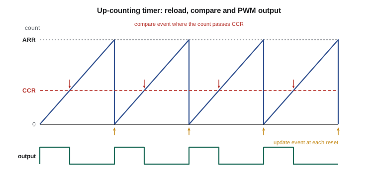
At its core, a timer is an up-counter that increments on each tick of its input clock. A prescaler divides the input clock first, so a 48 MHz clock with a prescaler of 48 gives 1 MHz ticks, one per microsecond. An auto-reload register sets the top count: when the counter reaches it, the counter resets to zero on the next tick and raises an update event, which can trigger an interrupt, start a DMA transfer or start an ADC conversion. The period of the update event is therefore the prescaler value times the reload value plus one, divided by the input clock. Counters come in 16-bit and 32-bit widths; some also count down or up and down alternately, which helps when generating center-aligned PWM for motors.
The plus-ones come from how the registers are defined on most microcontrollers: a prescaler register of 0 divides by 1, and a reload value of 999 gives 1,000 counts per period. Off-by-one errors here are common; a tick that should be 1.000 ms comes out at 1.001 ms, the clock drifts by 86 seconds a day, and nobody notices until timestamps from different nodes disagree.
Worked problem
Configuring a 1 ms tick
Timer 6 on the NS-4 runs from a 48 MHz timer clock. Find prescaler and reload values for an update interrupt every 1.000 ms, keeping the reload within 16 bits.
Show solution
- The period must contain 48 MHz × 1 ms = 48,000 timer clocks.
- \[ (PSC + 1)(ARR + 1) = 48000\]
- One choice is PSC + 1 = 48, giving 1 MHz ticks, and ARR + 1 = 1000.
- So PSC = 47 and ARR = 999; both fit in 16 bits.
Answer: Set PSC = 47 and ARR = 999. Another valid choice is PSC = 0, ARR = 47,999, which gives the finest resolution within the period; the 1 MHz version is easier to read in microseconds.
Output compare and PWM
Each timer has several channels, and each channel has a compare register. In output compare mode, when the counter equals the compare value, the channel can set, clear or toggle its output pin, raise an interrupt or trigger DMA, all without the core. Generating a precise pulse is then a matter of loading the compare register: the edge happens on exactly the right tick regardless of what the firmware is doing. In PWM mode, the channel drives its pin high at the start of each period and low when the counter passes the compare value, so the compare value sets the duty cycle directly. Because the hardware switches the pin, the PWM is jitter-free and costs no processor time once configured.
Changing a PWM duty cycle while the timer runs needs care. If firmware writes a new compare value at an arbitrary moment, the current period may get a glitch, for example a pulse that never ends if the new value is below the current count. Timers avoid this with preload, or shadow, registers: writes go into a buffer that is copied to the active compare register only at the next update event, so every period is complete and consistent. The NS-4's LED dimming code enables preload on every channel it uses.
Input capture
Input capture is the reverse of output compare. When an edge arrives on a channel's input pin, the timer copies the current count into the channel's capture register and raises a flag or interrupt. The timestamp is taken by hardware at the edge, accurate to one timer tick, no matter how long the interrupt takes to start. Two captures on rising edges give a period; a rising and a falling edge give a pulse width. Input filters on the channel can ignore pulses shorter than a set number of ticks, rejecting noise, and a capture prescaler can capture every second, fourth or eighth edge to measure high frequencies.
This is the right way to timestamp radar detections. The NS-4's radar module raises its detect line when a vehicle enters the beam. The old firmware handled a GPIO interrupt on that line and read a software millisecond counter inside the handler. When the processor was busy in a higher-priority interrupt, such as the modem receive handler during an upload, the GPIO handler started late, and its timestamp could be later than that of a vehicle detected just afterwards in the other lane, whose handler happened to run first. That was the field bug. Jonah's fix routes both lanes' detect lines to input-capture channels of a 32-bit timer counting microseconds, so the timestamps come from hardware at the edges and the handlers can run whenever convenient.
# Reconstructing event times from a free-running 16-bit capture timer at 1 MHz.
# The counter wraps every 65.536 ms; firmware counts overflows to extend it.
TOP = 1 << 16

def extend(captures):
    """captures: list of (overflow_count_at_service, raw_capture, overflow_pending)."""
    out = []
    for ovf, cap, pending in captures:
        # If an overflow happened but was not yet serviced, and the capture is small,
        # the capture belongs after the overflow.
        if pending and cap < TOP // 2:
            ovf += 1
        out.append(ovf * TOP + cap)
    return out

events = [(10, 65_500, False),   # just before a wrap
          (10, 12, True),        # just after the wrap, overflow interrupt not yet run
          (11, 900, False)]
t = extend(events)
print("extended times (us):", t)
print("intervals (us):", [b - a for a, b in zip(t, t[1:])])

# A 32-bit timer at 1 MHz needs no extension for a long time
wrap_32 = (1 << 32) / 1e6
print(f"32-bit timer at 1 MHz wraps after {wrap_32/60:.1f} minutes")extended times (us): [720860, 720908, 721796] intervals (us): [48, 888] 32-bit timer at 1 MHz wraps after 71.6 minutes
The 16-bit version shows the subtle race in extending a counter in software. If a capture occurs just after the counter wraps, but the overflow interrupt has not yet incremented the overflow count, the naive calculation puts the event 65.5 ms too early. The fix checks whether an overflow is pending and whether the capture value is small. A 32-bit timer counting microseconds wraps only every 71.6 minutes and makes such tricks rarer, which is why Jonah used one; the firmware still extends it to 64 bits for timestamps that span days.
Counting external events
A timer can take its clock from an external pin instead of the internal clock, turning it into an event counter. Pulses from a flow meter, a rotary encoder, an anemometer or a tachometer are counted entirely in hardware, with no interrupt per pulse. Reading the count at fixed intervals gives a frequency; reading it after a fixed number of counts gives a period. Some timers have a dedicated quadrature encoder mode that counts up or down according to the phase of two encoder signals, tracking the position of a motor shaft or a knob. Hardware counting can handle pulse rates of tens of megahertz, far beyond what interrupts could manage, and keeps counting while the core sleeps.
| Method | How it works | Best for | Resolution limit |
|---|---|---|---|
| Frequency counting | Count pulses for a fixed gate time | High frequencies | One count in the gate time |
| Period measurement | Capture the timer at successive edges | Low frequencies | One timer tick in one period |
| Reciprocal counting | Count both pulses and timer ticks over a gate | All frequencies | One timer tick over the gate |
| Pulse-width measurement | Capture on rising and falling edges | Duty cycle, PWM sensors | One timer tick |
Worked problem
Choosing a frequency measurement method
The radar module's status output is a square wave between 50 Hz and 5 kHz that encodes its internal temperature. The timer clock is 1 MHz. Compare the relative resolution of frequency counting with a 100 ms gate and period measurement, at 50 Hz and at 5 kHz.
Show solution
- Frequency counting with a 0.1 s gate counts 5 pulses at 50 Hz and 500 at 5 kHz; one count of uncertainty is 20 percent and 0.2 percent.
- Period measurement captures 20,000 ticks per period at 50 Hz and 200 ticks at 5 kHz; one tick of uncertainty is 0.005 percent and 0.5 percent.
- Period measurement is far better at low frequency, and counting is better at high frequency.
Answer: Use period measurement for this sensor, possibly averaging several periods at the high end, or use reciprocal counting, which keeps the error near one tick over the whole gate at any frequency.
The system tick and software timers
Almost every firmware project has a periodic interrupt, the system tick, that advances a global time counter, typically every millisecond. Cores often include a dedicated system timer for this purpose. Software timers, such as 'blink the LED every 500 ms' or 'retry the upload in 30 s', are then built on the tick by keeping a list of expiry times and checking it, either in the tick handler or in the main loop. The tick period is a compromise. A shorter tick gives finer timing but wakes the processor more often, which costs energy; the NS-4 originally ticked every millisecond even while waiting hours between uploads, wasting about a fifth of its sleep budget. Lesson 11 shows the tickless approach that programs a low-power timer to wake the processor only when the next software timer expires.
#define TICK_HZ 1000u
static volatile uint32_t ms_ticks;

void SysTick_Handler(void) { ms_ticks++; }

typedef struct { uint32_t due; uint32_t period; void (*fn)(void); } soft_timer_t;

void soft_timers_run(soft_timer_t *t, unsigned n)
{
    uint32_t now = ms_ticks;
    for (unsigned i = 0; i < n; i++) {
        if ((int32_t)(now - t[i].due) >= 0) {     /* wrap-safe comparison */
            t[i].due += t[i].period;
            t[i].fn();
        }
    }
}
Low-power timers and the real-time clock
Ordinary timers stop when the main clock stops, so they cannot wake the processor from deep sleep. Low-power timers run from the 32.768 kHz crystal or a low-frequency internal oscillator and keep counting in stop modes, waking the core at a programmed count. The real-time clock is a specialized low-power timer that keeps calendar time, seconds through years, with alarms and a periodic wake-up; it typically runs from a backup supply or the main battery and draws around a microamp. Crystal accuracy matters here: a 20 ppm crystal gains or loses up to 1.7 seconds a day, and crystal frequency also varies with temperature, following a parabola that drops about 0.034 ppm per degree squared away from 25 °C. The NS-4 corrects its clock from the cellular network once a day and adjusts a digital calibration register in the RTC to trim the drift between corrections.
At −40 °C, a winter night on a northern highway, that parabola predicts about −144 ppm, or 12 seconds a day slow, which is why the daily network correction and the temperature-compensated trim matter for timestamps that must agree across nodes.
# Search prescaler/reload pairs for a target update frequency and report the error
def best_settings(f_timer, f_target, max_psc=65536, max_arr=65536, n=3):
    best = []
    for psc in range(1, max_psc + 1):
        arr = round(f_timer / (f_target * psc))
        if 1 <= arr <= max_arr:
            f = f_timer / (psc * arr)
            err = (f - f_target) / f_target * 1e6     # ppm
            best.append((abs(err), psc - 1, arr - 1, f, err))
    best.sort()
    return best[:n]

for f_t in (48e6, 32.768e3):
    for target in (1000.0, 37.5):
        print(f"timer clock {f_t:>10,.0f} Hz, target {target} Hz")
        for _, psc, arr, f, err in best_settings(f_t, target):
print(f" PSC={psc:5d} ARR={arr:5d} f={f:12.6f} Hz error {err:+9.1f} ppm")timer clock 48,000,000 Hz, target 1000.0 Hz PSC= 0 ARR=47999 f= 1000.000000 Hz error +0.0 ppm PSC= 1 ARR=23999 f= 1000.000000 Hz error +0.0 ppm PSC= 2 ARR=15999 f= 1000.000000 Hz error +0.0 ppm timer clock 48,000,000 Hz, target 37.5 Hz PSC= 19 ARR=63999 f= 37.500000 Hz error +0.0 ppm PSC= 24 ARR=51199 f= 37.500000 Hz error +0.0 ppm PSC= 31 ARR=39999 f= 37.500000 Hz error +0.0 ppm timer clock 32,768 Hz, target 1000.0 Hz PSC= 0 ARR= 32 f= 992.969697 Hz error -7030.3 ppm PSC= 2 ARR= 10 f= 992.969697 Hz error -7030.3 ppm PSC= 10 ARR= 2 f= 992.969697 Hz error -7030.3 ppm timer clock 32,768 Hz, target 37.5 Hz PSC= 0 ARR= 873 f= 37.491991 Hz error -213.6 ppm PSC= 1 ARR= 436 f= 37.491991 Hz error -213.6 ppm PSC= 18 ARR= 45 f= 37.491991 Hz error -213.6 ppm
From 48 MHz, both 1 kHz and 37.5 Hz come out exactly. From the 32.768 kHz low-power clock, 1 kHz is impossible to hit exactly: the closest divisor, 33, gives about 993 Hz, an error of about −7,000 ppm. That is fine for waking up to check a sensor but useless as a timebase, which is why the NS-4 keeps time with the RTC's binary second counter and uses the low-power timer only for wake-ups.
Common mistakes
MistakeForgetting the plus-one in prescaler and reload registers.
InsteadOn most timers the division is PSC + 1 and the period ARR + 1 counts; check the reference manual.
MistakeTimestamping events inside an interrupt handler with a software counter.
InsteadUse input capture so the hardware records the count at the edge, independent of interrupt latency.
MistakeWriting a new PWM compare value without preload.
InsteadEnable the preload register so changes take effect at the next update, avoiding glitches.
MistakeExtending a short counter without handling a pending overflow.
InsteadCheck for an unserviced overflow and a small capture value, or use a wider timer.
MistakeUsing a fast periodic tick in a battery device that mostly sleeps.
InsteadUse a low-power timer or tickless scheduling to wake only when work is due.
Summary and key terms
- A timer is a prescaled counter with reload, compare and capture logic.
- The update period is (PSC + 1)(ARR + 1) divided by the timer clock.
- Output compare and PWM change pins in hardware at exact counts; preload avoids glitches.
- Input capture timestamps edges in hardware, unaffected by interrupt latency.
- Timers can count external pulses and decode quadrature encoders without interrupts.
- Period measurement suits low frequencies, counting suits high ones, reciprocal counting suits both.
- Low-power timers and the RTC run in sleep from a 32.768 kHz crystal whose accuracy varies with temperature.
- Prescaler
- A divider that slows the clock feeding a timer counter.
- Auto-reload register
- The value at which a timer counter wraps and raises an update event.
- Update event
- The event a timer raises when its counter wraps; it can trigger interrupts, DMA or other peripherals.
- Output compare
- A timer mode that acts, such as toggling a pin, when the count equals a stored value.
- Input capture
- A timer mode that copies the count into a register when an input edge occurs.
- Preload register
- A buffer that holds a new timer setting until the next update event.
- System tick
- A periodic interrupt that advances the firmware's notion of time.
- Real-time clock
- A low-power timer that keeps calendar time and runs in sleep modes.
Practice problems
Work each problem on paper first, then reveal the answer to check.
A 72 MHz timer must produce a 50 Hz update. Give one valid PSC and ARR pair within 16 bits.
Show answer
72 MHz ÷ 50 = 1,440,000 counts; PSC = 71 (1 MHz ticks) and ARR = 19,999.
A 16-bit timer counts at 2 MHz. How long until it wraps?
Show answer
65,536 ÷ 2 MHz = 32.768 ms.
Two rising-edge captures read 1,250 and 3,750 on a 1 MHz timer. What is the signal's frequency?
Show answer
Period 2,500 µs, so 400 Hz.
Why does a 20 ppm crystal clock need correction for a node that must timestamp to the second over months?
Show answer
20 ppm is up to 1.7 s per day, over 50 s per month; temperature adds more drift.
Lesson quiz · 5 questions
Score 60% or more to complete this lesson.
Create a free account to save your progress, take quizzes and earn a certificate.