
CIV-440 · Lesson 6 of 12 · 22 min
Braced and anchored excavations
Deep excavations in cities and on constrained sites are supported by walls held by several levels of struts or anchors. Such walls do not behave like the cantilever and anchored walls of lesson 5. They are installed and supported in stages as the excavation deepens, each level of support is installed before much movement has occurred, and the earth pressure on them is neither active nor at rest, nor distributed as a triangle. Design is based instead on apparent pressure envelopes derived from measured strut loads. The base of the excavation must also be checked for heave and, where there is water under pressure below, for uplift. This lesson designs the support for the new wet well of the Kestrel Bay lift station.
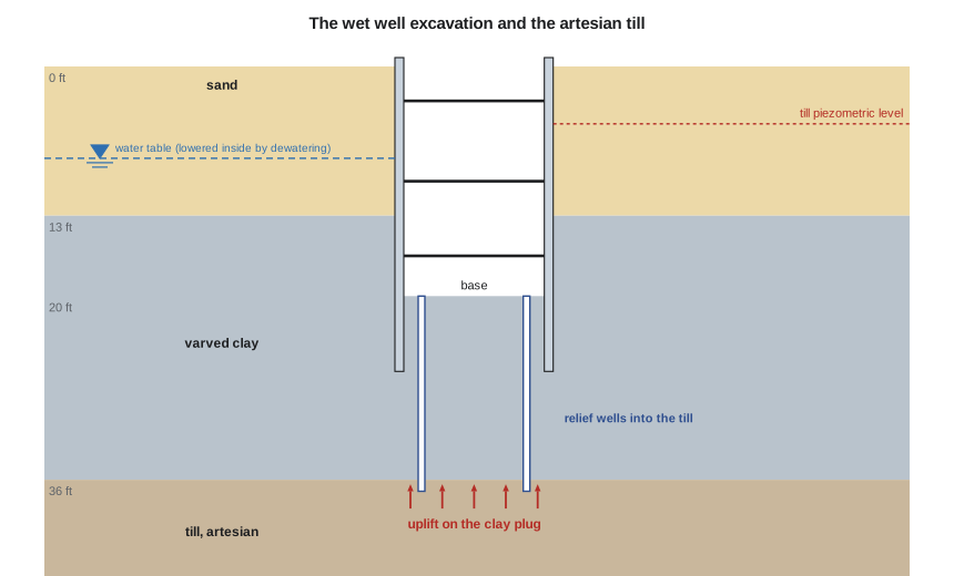
The lift station built in Foundation Engineering needs a second wet well to serve phase 3. The new well is 13 ft wide and 26 ft long, with its base 20 ft below grade: through the sand, below the water table and 7 ft into the varved clay. The clay below the base extends to the artesian till at 36 ft, where the piezometric level is only 5 ft below grade. The team has worried about that till since Soil Mechanics.
Why apparent pressure envelopes
In the 1940s and 1950s, Terzaghi and Peck measured strut loads in braced cuts for the subways of Berlin, Chicago and other cities. They found that the loads did not follow any triangular distribution. As each level of struts is installed, the wall above is held in place, while the wall below continues to yield inward as excavation proceeds. The soil near the top therefore stays close to its initial state, arching transfers load to the stiffer struts, and the total thrust can exceed the active value. To design struts, Terzaghi and Peck back-calculated, for each cut, a uniform pressure that would reproduce the largest measured strut load at each level, and drew envelopes around the results. The envelopes are not real pressure distributions; they are design tools for the struts.
The envelopes, as given in most manuals, are:
- For sands: a uniform pressure of \(0.65K_a\gamma H\) over the full height.
- For soft to medium clays, with \(\gamma H/s_u > 4\): a pressure rising from zero at the top to \(K\gamma H\) at \(0.25H\) and uniform below, with \(K = 1 - m\,4s_u/(\gamma H)\) and \(m = 1\) unless the base is unstable.
- For stiff clays, with \(\gamma H/s_u \le 4\): a trapezoid rising from zero to between \(0.2\gamma H\) and \(0.4\gamma H\) at \(0.25H\), uniform to \(0.75H\) and falling to zero at the base.
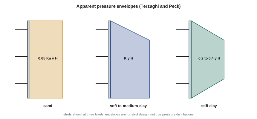
The FHWA manual on ground anchors and anchored systems and the Canadian Foundation Engineering Manual give versions of these envelopes, with recommendations on surcharges, water pressure and layered soils. In layered ground, such as sand over clay, an envelope based on a weighted average of the soils, or the larger of the envelopes for each, is used with judgment. Water pressure is added to the envelope for walls that are impermeable and not dewatered.
Strut and anchor loads
With the envelope chosen, each strut level carries the pressure over its tributary height, from midway to the level above to midway to the level below, or to the top or the base. The wall itself is analyzed as a continuous beam on the strut supports. Struts are steel pipes or wide-flange sections spanning between walers, with preloading by jacks to about half their design load to reduce movement. Corner braces and rakers are used where the excavation is too wide for cross struts.
Ground anchors, or tiebacks, avoid struts across the excavation, leaving it clear for construction. A tieback consists of a steel bar or strand tendon in a drilled hole, with an unbonded free length that passes through the potential failure wedge and a grouted bond length beyond it. The bond length is designed from the ultimate bond stress of the soil-grout interface:
with a factor of safety of about 2 on the bond, typical bond stresses of 2,000 to 8,000 psf in dense sands and gravels, much less in clays, and every anchor proof-tested to about 1.33 times its design load before it is locked off, with a few given longer performance tests. The anchors must lie within the owner's property, or within easements under neighboring land.
Basal heave
An excavation in clay can fail by the clay beneath and beside it flowing in and lifting the base, a bearing capacity failure in reverse. The weight of the soil beside the excavation, plus any surcharge, is the load; the undrained strength of the clay is the resistance. Bjerrum and Eide's analysis uses Skempton's bearing capacity factors:
with \(N_c\) depending on the depth and the plan shape of the excavation, from 5.14 for a long shallow cut up to 9 for a deep square one. A factor of safety of at least 1.5 is usually required. When it is lower, the walls are extended deeper into firm soil below the base, or the excavation is made in short sections. The stability number \(\gamma H/s_u\) also controls the movement of the ground around the excavation: values above about 6 are associated with large movements.
Uplift and hydraulic failure of the base
Where a layer of clay at the base of an excavation rests on a permeable layer with water under pressure, the clay can be lifted bodily when its weight is no longer enough to balance the water pressure beneath it. The factor of safety is simply
where \(t\) is the remaining thickness of clay and \(u_{base}\) the pore pressure at its underside. This was the hazard found for the pump station excavation in Soil Mechanics, and the new wet well is deeper. Uplift failures happen suddenly: the base cracks, water and sand boil into the excavation, and the walls lose their passive support. They are prevented by relief wells that lower the pressure in the permeable layer, by a thicker clay plug left in place under a tremie concrete slab, or by extending a cutoff wall into the permeable layer.
Worked problem
Support of the wet well excavation
The excavation is 20 ft deep and 13 ft wide, through 13 ft of sand (\(\phi' = 34^\circ\), \(\gamma = 121\) pcf, drained by dewatering wells) into clay with \(s_u = 1{,}150\) psf and \(\gamma = 115\) pcf. Struts are at 3, 10 and 16.5 ft depth and 10 ft spacing, with a surcharge of 250 psf. The till at 36 ft has its piezometric level 5 ft below grade.
Show solution
- Average unit weight 119 pcf; stability number:
- \[\gamma H/s_u = 119(20)/1{,}150 = 2.07 \;\le 4 \;\Rightarrow\; \text{stiff clay envelope}\]
- \[p = 0.4\gamma H = 951\ \text{psf (sand envelope } 0.65K_a\gamma H = 437\text{)}\]
- Strut loads from tributary areas, with \(K_a q\) added:
- \[47{,}700,\ 69{,}000\ \text{and}\ 50{,}200\ \text{lb per strut}\]
- Basal heave, with \(N_c = \) 7.39:
- \[FS = 1{,}150(7.39)/(119 \times 20 + 250) = 3.24\]
- Uplift of the clay plug, 16 ft thick:
- \[FS = \frac{115(16)}{62.4(36 - 5)} = \frac{1{,}840}{1{,}934} = 0.95\]
Answer: The struts and the base are adequate against heave, but the clay plug would be lifted by the till water before the excavation reached its base. Relief wells into the till, pumped to keep its piezometric level at least 16 ft below grade, raise the factor of safety to 1.47.
The script computes the envelopes, the strut loads, the basal heave and uplift checks, and the bond length that tiebacks would need.
# Braced excavation for the new lift-station wet well and trunk sewer connection
from math import tan, radians, pi
UNITS = "US"
SI = UNITS == "SI"
L, F, P = ("m", "kN/m", "kPa") if SI else ("ft", "lb/ft", "psf")
if SI:
    He, Be, zs, g_sand, phi, g_clay, su, z_clay, z_till, h_pz, gw, q = 6.0, 4.0, 4.0, 19.0, 34.0, 18.0, 55.0, 4.0, 11.0, 1.5, 9.81, 12.0
    struts, spacing = (1.0, 3.0, 5.0), 3.0
else:
    He, Be, zs, g_sand, phi, g_clay, su, z_clay, z_till, h_pz, gw, q = 20.0, 13.0, 13.0, 121.0, 34.0, 115.0, 1150.0, 13.0, 36.0, 5.0, 62.4, 250.0
    struts, spacing = (3.0, 10.0, 16.5), 10.0
Ka = tan(radians(45 - phi / 2)) ** 2
gavg = (g_sand * zs + g_clay * (He - zs)) / He
# apparent pressure envelopes (Terzaghi and Peck, as given in most manuals)
p_sand = 0.65 * Ka * gavg * He
Ns = gavg * He / su
p_clay = 0.4 * gavg * He                     # stiff clay trapezoid, upper end of the 0.2 - 0.4 gamma H range
print(f"Excavation depth {He:g} {L}, width {Be:g} {L}; average unit weight {gavg:.1f}; stability number gamma H / su = {Ns:.2f}")
print(f"Apparent pressure: sand rectangle 0.65 Ka gamma H = {p_sand:.1f} {P}; stiff clay trapezoid 0.4 gamma H = {p_clay:.1f} {P}")
pq = Ka * q
def pressure(z):                              # trapezoid for the clay case (0.25H ramps) plus surcharge, the envelope adopted
    r = min(z / (0.25 * He), 1.0, (He - z) / (0.25 * He))
    return max(p_clay * r, p_sand) + pq
# tributary-area strut loads (pressure integrated between midpoints)
n = 2000; edges = [0.0] + [(struts[i] + struts[i + 1]) / 2 for i in range(len(struts) - 1)] + [He]
for i, zst in enumerate(struts):
    a, b = edges[i], edges[i + 1]
    Fz = sum(pressure(a + (k + 0.5) * (b - a) / n) for k in range(n)) * (b - a) / n
    print(f"  strut level {i+1} at {zst:g} {L}: {Fz:.1f} {F} of wall -> {Fz*spacing:.0f} {'kN' if SI else 'lb'} per strut at {spacing:g} {L} spacing")
# basal heave of the clay (Bjerrum and Eide, with Skempton's factors); length of the wet well 8 m | 26 ft
Le = 8.0 if SI else 26.0
Nc = min(5.14 * (1 + 0.2 * Be / Le) * (1 + 0.2 * min(He / Be, 2.5)), 9.0)       # Skempton-type factor for a rectangular base
FSh = su * Nc / (gavg * He + q)
print(f"\nBasal heave (Bjerrum and Eide): Nc = {Nc:.2f}, FS = su Nc / (gamma H + q) = {FSh:.2f}")
# uplift of the clay plug from the artesian till
t_clay = z_till - He; sig = g_clay * t_clay; u = gw * (z_till - h_pz)
print(f"Clay below the base: {t_clay:g} {L}; weight {sig:.1f} {P}; till pore pressure {u:.1f} {P}; FS against uplift = {sig/u:.2f}")
for target in ((5.0, 6.5) if SI else (16.0, 21.0)):
    u2 = gw * (z_till - target)
    print(f"  lower the till head to {target:g} {L} below grade with relief wells: u = {u2:.1f} {P}, FS = {sig/u2:.2f}")
# ground anchors instead of cross-struts: bond length
T = 180.0 if SI else 40000.0; d = 0.15 if SI else 0.5; tau = 55.0 if SI else 1150.0      # anchor design load, grout diameter, ultimate bond taken as about su in the clay
Lb = 2.0 * T / (pi * d * tau)
print(f"\nGround anchor alternative: design load {T:g}, grout diameter {d:g} {L}, ultimate bond in the clay {tau:g} {P}: bond length for FS 2 = {Lb:.1f} {L}")Excavation depth 20 ft, width 13 ft; average unit weight 118.9; stability number gamma H / su = 2.07 Apparent pressure: sand rectangle 0.65 Ka gamma H = 437.0 psf; stiff clay trapezoid 0.4 gamma H = 951.2 psf strut level 1 at 3 ft: 4766.1 lb/ft of wall -> 47661 lb per strut at 10 ft spacing strut level 2 at 10 ft: 6897.7 lb/ft of wall -> 68977 lb per strut at 10 ft spacing strut level 3 at 16.5 ft: 5021.6 lb/ft of wall -> 50216 lb per strut at 10 ft spacing Basal heave (Bjerrum and Eide): Nc = 7.39, FS = su Nc / (gamma H + q) = 3.24 Clay below the base: 16 ft; weight 1840.0 psf; till pore pressure 1934.4 psf; FS against uplift = 0.95 lower the till head to 16 ft below grade with relief wells: u = 1248.0 psf, FS = 1.47 lower the till head to 21 ft below grade with relief wells: u = 936.0 psf, FS = 1.97 Ground anchor alternative: design load 40000, grout diameter 0.5 ft, ultimate bond in the clay 1150 psf: bond length for FS 2 = 44.3 ft
Reading the results
Two features stand out. First, the stiff clay envelope governs over the sand envelope, by about a factor of two, because the excavation is mostly in clay and the trapezoid uses a pressure coefficient of 0.4 applied to the total overburden. The middle strut, with the largest tributary height, is the most heavily loaded. Second, the uplift check, not heave or strut loads, controls the design: without relief wells the base would fail when the excavation was about 3 ft above its final level. This is the kind of failure that is quick and dangerous, and the reason the design report names it first.
Tiebacks were considered so that the excavation would be free of struts. With an ultimate bond of about \(s_u\) in the clay, the bond length for a 40,000 lb anchor would be 44 ft, reaching under Ridgeway Road and outside the city's property. Cross struts are cheaper and simpler for an excavation only 13 ft wide, and they were chosen.
Dewatering and movement control
The sand above the clay must be dewatered before it is excavated below the water table, or it will run through the lagging. Wellpoints or deep wells in the sand lower the water table below the excavation level in the sand, while the relief wells in the till are a separate system with their own discharge, monitoring and backup power. Pumped water is discharged to the storm sewer under a permit, after settlement of fines.
Lowering the water table in the sand, and the till pressure, increases the effective stress in the clay and could settle nearby structures. The existing pump station is on its own foundation; the team estimates the settlement of the yard and the old wet well at a few millimeters for the short duration of pumping and sets survey points on both. Ground movements around the excavation are also controlled by stiff walls, prompt installation and preloading of struts, and avoiding over-excavation below each strut level. Peck's classification of settlement behind braced cuts in sand and stiff clay suggests settlements of less than about 1 % of the depth, which here is less than 2.4 in. at the wall and decreasing with distance.
| Check | Result | Required | Action |
|---|---|---|---|
| Strut loads (stiff clay envelope) | 47.7 / 69.0 / 50.2 kips | – | design struts and walers |
| Basal heave | FS 3.24 | ≥ 1.5 | none |
| Uplift of the clay plug, no relief | FS 0.95 | ≥ 1.3 | unacceptable |
| Uplift with relief wells | FS 1.47 | ≥ 1.3 | relief wells, piezometers, alarms |
| Tieback alternative | bond 44 ft | – | rejected: off the property |
Practical points
- Use apparent pressure envelopes for multi-level braced and anchored walls, not triangular pressures.
- Check basal heave in clay with the Bjerrum and Eide factors and the stability number.
- Always look for water under pressure below the base, and check uplift of any clay plug.
- Design dewatering and relief wells as part of the support system, with monitoring and backup.
- Proof-test every ground anchor before lock-off.
Common mistakes
MistakeUsing the active triangle to design the struts of a braced cut.
InsteadStrut loads come from the apparent pressure envelopes.
MistakeChecking basal heave but not uplift from a confined aquifer below.
InsteadUplift can govern even when heave is satisfactory.
MistakeRelying on relief wells without monitoring or backup power.
InsteadIf the pumps stop, the base can fail within hours; piezometers, alarms and standby power are part of the design.
MistakePlacing tieback bond zones under neighboring property without permission.
InsteadAnchors need easements or must stay within the property.
Summary and key terms
- Multi-level braced walls are designed with apparent pressure envelopes from measured strut loads.
- Sand: \(0.65K_a\gamma H\); stiff clay: a trapezoid of 0.2 to 0.4\(\gamma H\); soft clay: \(K\gamma H\) below 0.25\(H\).
- Basal heave: \(FS = s_u N_c/(\gamma H + q) \ge 1.5\).
- Uplift: \(FS = \gamma t/u\); relief wells, a thicker plug or a cutoff are the remedies.
- Tieback bond: \(L_b = FS\,T/(\pi d\tau_{ult})\), with every anchor proof-tested.
- The wet well: struts at 47.7/69.0/50.2 kips; heave 3.24; uplift 0.95 rising to 1.47 with relief wells.
- Braced excavation
- An excavation supported by walls and horizontal struts at several levels.
- Apparent pressure envelope
- A design pressure diagram for braced walls derived from measured strut loads.
- Strut
- A compression member spanning across an excavation between walers.
- Tieback
- A grouted ground anchor that holds an excavation wall from behind.
- Basal heave
- Failure of an excavation in clay by the soil beneath and beside it flowing upward into the base.
- Stability number
- The ratio \(\gamma H/s_u\), which indicates the likelihood of base instability and large movements.
- Relief well
- A well that lowers the water pressure in a confined permeable layer.
- Proof test
- A load test of every ground anchor to above its design load before lock-off.
Practice problems
Work each problem on paper first, then reveal the answer to check.
A braced cut 26 ft deep in sand with \(K_a = 0.28\) and \(\gamma = 120\) pcf. Find the apparent pressure.
Show answer
\(0.65(0.28)(120)(26) = 568\) psf.
An excavation 16 ft deep in clay with \(s_u = 600\) psf and \(\gamma = 115\) pcf has \(N_c = 6.5\). Find the factor of safety against basal heave with no surcharge.
Show answer
\(FS = 600(6.5)/1{,}840 = 2.12\).
13 ft of clay, \(\gamma = 115\) pcf, lies over a sand with a piezometric level 6.5 ft below the excavation base. If the base of the clay is 13 ft below the excavation, find the uplift factor of safety.
Show answer
The water stands 6.5 ft above the base of the clay, so \(u = 62.4(6.5) = 406\) psf and \(FS = 115(13)/406 = 3.7\).
Why are struts preloaded?
Show answer
To take up slack and initial deformation, reducing the movement of the wall and the ground behind it.
Lesson quiz · 5 questions
Score 60% or more to complete this lesson.
Create a free account to save your progress, take quizzes and earn a certificate.