
CIV-440 · Lesson 10 of 12 · 19 min
Ground improvement
When the ground is too weak or too compressible for what is to be built on it, the engineer has three choices: go around it, go through it with deep foundations, or improve it. Ground improvement changes the soil itself, by loading it, draining it, densifying it, reinforcing it, replacing part of it or binding it with cement. It has grown from a set of special techniques into a routine part of geotechnical practice, especially for embankments, storage areas and industrial floors on soft ground, where piles would be uneconomical. This lesson surveys the main methods and chooses one for the approach embankment of Ridgeway Road at the Kestrel Creek culvert.
North of the culvert, the realigned road rises on an embankment up to 10 ft high over a length of about 260 ft. The embankment sits on the familiar profile: 13 ft of sand over 23 ft of varved clay, drained at both faces. The new box culvert from Hydraulics & Hydrology is founded on the sand and will hardly settle. The road authority asks for no more than 1 in. of settlement after paving, so that a bump does not form at the culvert, and wants the road paved in the season after the embankment is built.
Preloading and vertical drains
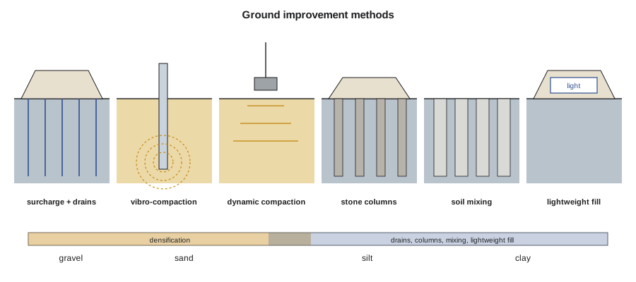
Preloading places a temporary load, usually a fill surcharge, on the ground before construction, so that consolidation settlement happens before the permanent works are built. The surcharge is then removed, and the clay, now overconsolidated, is reloaded along its stiff recompression line. Foundation Engineering used this method for the garage. The difficulty is time: clay consolidates slowly when water must drain vertically over half its thickness. Prefabricated vertical drains (PVDs), band drains of a plastic core in a filter sleeve, installed by a mandrel at spacings of about 3 to 6 ft, shorten the drainage path to half the drain spacing and make use of the larger horizontal permeability of layered clays. Radial consolidation follows Barron's and Hansbo's solutions, with the time to a degree of consolidation \(U_h\) of
where \(d_e\) is the diameter of the soil cylinder drained by each drain, \(1.05\) times the spacing for a triangular pattern, and \(d_w\) is the equivalent diameter of the drain. Smear from installation and the flow resistance of long drains add terms to \(F(n)\) and slow the process; in varved clays, with their silty partings, the horizontal coefficient of consolidation is often several times the vertical.
Densification of granular soils
Loose sands and fills are densified by vibration or impact. Vibro-compaction uses a large vibrating probe, lowered into the ground with water or air jetting, which rearranges the grains into a denser packing around it. Dynamic compaction drops a weight of 10 to 30 tons from 30 to 100 ft onto the ground in a grid, densifying the soil to a depth of roughly \(0.5\sqrt{WH}\) in meters, with \(W\) in metric tons and \(H\) in meters. Both work best in clean sands and gravels with few fines; their effect is checked by CPT or SPT before and after. They are used to reduce settlement and to reduce the risk of liquefaction in seismic areas, which is not the problem at Kestrel Bay.
Columns: stone columns, rigid inclusions and soil mixing
In soft clays and silts, which vibration cannot densify, columns of stronger material are formed in the ground. Stone columns are built by vibro-replacement: a vibrating probe makes a hole, crushed stone is fed down it and compacted in lifts, and the column is expanded against the surrounding clay. The columns carry a larger share of the load than the clay around them, and they also act as vertical drains. Priebe's method estimates the basic improvement factor, the ratio of the settlement without columns to the settlement with them, from the area replacement ratio \(A_c/A\) and the friction angle of the stone:
Rigid inclusions, unreinforced concrete or grout columns with a granular load transfer platform above them, carry most of the load down to a firmer layer and reduce settlement much more. Deep soil mixing blends cement or lime into the soil in place with rotating augers or paddles, forming columns, panels or blocks of stabilized soil with a strength of a few hundred kilopascals to a few megapascals. Its stiffness is many times that of the clay, so even a modest replacement ratio greatly reduces settlement.
Lightweight fill, reinforcement and other methods
Reducing the load is sometimes the simplest way to reduce settlement. Lightweight fills, such as expanded polystyrene (EPS) geofoam blocks, foamed glass aggregate, expanded shale or wood chips, replace part of the embankment with material weighing from about one fiftieth to one fifth as much as soil. Placed so that the weight of the excavated soil roughly balances the new load, they can make a fill on soft ground nearly settlement-free. EPS must be protected from fuel spills and from buoyancy where it lies below the flood level.
Basal reinforcement, layers of high-strength geotextile or geogrid at the base of an embankment, increases its stability on soft ground and is often combined with columns. Grouting, by permeation, compaction or jet grouting, fills voids, strengthens soil or forms cutoffs and underpinning. Electro-osmosis and vacuum consolidation, which applies a vacuum under an airtight membrane instead of a fill surcharge, are used in special cases. Each method has a range of soils it suits; the chart of applicable methods against grain size, from gravels to clays, is one of the most useful in the subject.
Worked problem
Settlement of the approach embankment and the options
The embankment applies 1,250 psf over a wide area. Use the clay parameters from Soil Mechanics (\(C_c = 0.316\), \(C_r = 0.047\), \(e_0 = 1.06\), preconsolidation pressure 900 psf above the in-situ stress, \(c_v = \) 27 ft²/yr, double drainage of the 23 ft layer). Find the settlement and how long it takes, then the effect of PVDs, lightweight fill, stone columns and soil mixing.
Show solution
- The settlement, computed in sublayers with recompression up to the preconsolidation pressure and virgin compression beyond it:
- \[s_c = 3.1\ \text{in.} \qquad U = 0.51\ \text{after 1 year}, \; 0.89\ \text{after 4 years}\]
- PVDs at 5 ft in a triangular pattern, \(d_e = \) 5.2 ft, \(d_w = \) 2.6 in., \(n = 24\), \(F(n) = 2.42\), \(c_h = 3c_v\):
- \[t_{90} \approx 2.8\ \text{months}\]
- Lightweight fill for 6.5 ft of the height (about 25 pcf):
- \[\Delta\sigma = 585\ \text{psf} \;\Rightarrow\; s_c = 0.8\ \text{in.}\]
- Stone columns with \(\phi_c = 40^\circ\): \(n_0 = 1.83\) at \(A_c/A = 0.15\) and 2.57 at 0.25; soil mixing at 20 to 30 % replacement reduces the settlement to 0.3 to 0.4 in..
Answer: Untreated, the embankment would settle 3.1 in., but only half of it within a year: the road could not be paved on schedule. PVDs finish the consolidation in a few months, and lightweight fill keeps the settlement within the limit without waiting at all.
The script computes the settlement and its time course, and the effect of each method.
# Ground improvement options for the 3 m | 10 ft approach embankment over the varved clay
from math import log10, log, tan, radians, exp, pi, sqrt
UNITS = "US"
SI = UNITS == "SI"
L, P = ("m", "kPa") if SI else ("ft", "psf")
k = 1.0 if SI else 3.281; ks = 1.0 if SI else 20.885          # length and stress conversion (SI to US)
# clay layer from CIV-340 (computed in SI internally)
z_top, z_bot, Cc, Cr, e0, POP, cv = 4.0, 11.0, 0.316, 0.047, 1.06, 45.0, 2.5
g_sand, gsub_sand, g_clay, zw, gw = 18.0, 9.99, 18.0, 2.5, 9.81
def sig0(z):
    s = g_sand * min(z, zw) + gsub_sand * max(0, min(z, z_top) - zw)
    return s + (g_clay - gw) * max(0, z - z_top)
def settlement(dq, n=14):
    tot = 0.0; dz = (z_bot - z_top) / n
    for i in range(n):
        z = z_top + (i + 0.5) * dz; s0 = sig0(z); sp = s0 + POP; sf = s0 + dq
        if sf <= sp: de = Cr * log10(sf / s0)
        else: de = Cr * log10(sp / s0) + Cc * log10(sf / sp)
        tot += de / (1 + e0) * dz
    return tot
def U_vertical(t, Hdr=3.5):
    Tv = cv * t / Hdr ** 2
    return min(1.0, sqrt(4 * Tv / pi)) if Tv < 0.2 else 1 - 8 / pi ** 2 * exp(-pi ** 2 * Tv / 4)
fill_h, g_fill = 3.0, 20.0
dq = fill_h * g_fill
s_full = settlement(dq)
out = lambda m: f"{m*1000:.0f} mm" if SI else f"{m*39.37:.1f} in."
print(f"Embankment {fill_h*k:.0f} {L} of fill: load {dq*ks:.0f} {P}; consolidation settlement {out(s_full)}")
for t in (0.5, 1, 2, 4, 8):
    print(f"  without drains, after {t:g} yr: U = {U_vertical(t):.2f}, settlement {out(s_full*U_vertical(t))}")
# (a) prefabricated vertical drains, 1.5 m triangular, Hansbo with no smear, ch = 3 cv
s_pvd = 1.5; de = 1.05 * s_pvd; dw = 0.066; nr = de / dw; Fn = log(nr) - 0.75; ch = 3 * cv
def U_radial(t): return 1 - exp(-8 * ch * t / (de ** 2 * Fn))
t90 = -log(0.1) * de ** 2 * Fn / (8 * ch)
print(f"(a) PVDs at {s_pvd*k:.1f} {L} triangular: 90 % consolidation in {t90*12:.1f} months (radial flow only)")
# (b) lightweight fill: 2 m | 6.5 ft of foamed glass aggregate (about 4 kN/m3 | 25 pcf placed) under 1 m | 3 ft of soil
dq_lw = 1.0 * g_fill + 2.0 * 4.0
print(f"(b) lightweight fill: load {dq_lw*ks:.0f} {P}; settlement {out(settlement(dq_lw))} (stays in recompression)")
# (c) stone columns, Priebe basic improvement factor
phic = 40.0; Kac = tan(radians(45 - phic / 2)) ** 2
for ar in (0.15, 0.25):
    n0 = 1 + ar * ((5 - ar) / (4 * Kac * (1 - ar)) - 1)
    print(f"(c) stone columns, area ratio {ar:.2f}: Priebe n0 = {n0:.2f}, settlement about {out(s_full / n0)}")
# (d) deep soil mixing columns: settlement reduced by the stiffness of the composite
E_col, E_clay = 100.0, 3.0                       # MPa (about 14.5 and 0.44 ksi), column and clay constrained moduli (illustrative)
for ar in (0.20, 0.30):
    Ec = ar * E_col + (1 - ar) * E_clay
    mod = f"{Ec:.1f} MPa" if SI else f"{Ec*0.145:.2f} ksi"
    print(f"(d) soil mixing, area ratio {ar:.2f}: composite modulus {mod}, settlement about {out(s_full * E_clay / Ec)}")
# undrained stability of the embankment on the clay (bearing type check)
su = 55.0
print(f"Undrained stability of the {fill_h*k:.0f} {L} fill: FS = 5.14 su/(gamma H) = {5.14*su/dq:.1f}")Embankment 10 ft of fill: load 1253 psf; consolidation settlement 3.1 in. without drains, after 0.5 yr: U = 0.36, settlement 1.1 in. without drains, after 1 yr: U = 0.51, settlement 1.6 in. without drains, after 2 yr: U = 0.70, settlement 2.2 in. without drains, after 4 yr: U = 0.89, settlement 2.8 in. without drains, after 8 yr: U = 0.99, settlement 3.1 in. (a) PVDs at 4.9 ft triangular: 90 % consolidation in 2.8 months (radial flow only) (b) lightweight fill: load 585 psf; settlement 0.8 in. (stays in recompression) (c) stone columns, area ratio 0.15: Priebe n0 = 1.83, settlement about 1.7 in. (c) stone columns, area ratio 0.25: Priebe n0 = 2.57, settlement about 1.2 in. (d) soil mixing, area ratio 0.20: composite modulus 3.25 ksi, settlement about 0.4 in. (d) soil mixing, area ratio 0.30: composite modulus 4.65 ksi, settlement about 0.3 in. Undrained stability of the 10 ft fill: FS = 5.14 su/(gamma H) = 4.7
Choosing a method
Every method in the table can meet the settlement limit. The choice turns on cost, time, risk and the conditions at the culvert. The team scores them with the client:
| Method | Residual settlement | Time | Relative cost | Comment |
|---|---|---|---|---|
| No treatment | about 1.5 in. after 1 year | fails the schedule | – | bump at the culvert |
| PVDs with a surcharge | under 0.4 in. | 4–5 months | low | needs time and surcharge fill |
| Lightweight fill | about 0.8 in. | none | high per unit volume | best next to the culvert |
| Stone columns | 1.2–1.7 in., mostly fast | short | medium | columns also drain |
| Deep soil mixing | 0.3–0.4 in. | short | high | more than needed |
The adopted scheme combines two methods. For most of the embankment, PVDs at 5 ft triangular spacing are installed through a sand working platform and the embankment is built with a temporary surcharge of about 3 ft of extra fill, left for four to five months and then moved along or removed. For the last 50 ft before the culvert, where the culvert's own foundation does not settle and the difference would show as a bump, and where vertical drains could not be installed close to the structure, the lower part of the embankment is built of foamed glass aggregate wrapped in geotextile. Settlement plates and piezometers in the clay, read weekly, show when the consolidation is complete and the surcharge can come off. That is the observational method again.
Stability is not a concern for this embankment: the undrained factor of safety of a 10 ft fill on clay with \(s_u = 1{,}150\) psf is about 4.7. On softer clays, or for higher fills, the rate of filling over drains is controlled so that the clay gains strength as it consolidates, which is called staged construction.
Verification
Ground improvement is verified by testing, not by the specification alone. For drains and preloading, settlement plates, piezometers and inclinometers show the progress of consolidation, and the Asaoka method fits the settlement record to predict its final value. For densification, CPT or SPT before and after treatment, and sometimes load tests. For columns, the installation records of each column (depth, stone or binder quantity, energy), load tests on single columns or groups, and cores of soil mixing columns tested for strength. The contract should define the acceptance criteria before work starts.
Practical points
- Match the method to the soil: vibration for sands, drains and columns for clays, lightweight fill where load must be reduced.
- Combine methods where conditions change along the alignment, especially at structures.
- Account for smear and well resistance in drain design, and for the horizontal \(c_h\) of layered clays.
- Specify the acceptance criteria and the testing before the work starts.
- Monitor preloading and remove the surcharge on the evidence of the instruments.
Common mistakes
MistakeUsing vertical consolidation alone to estimate the time for a site with PVDs.
InsteadRadial flow to the drains governs; use Barron's or Hansbo's solution.
MistakeSpecifying vibro-compaction in clay.
InsteadVibration does not densify clay; use stone columns or other column methods.
MistakePlacing EPS geofoam below the flood level without checking buoyancy.
InsteadEPS floats; it needs enough cover to resist uplift.
MistakeRemoving a surcharge on a fixed date.
InsteadRemove it when the settlement and piezometer records show the target consolidation.
Summary and key terms
- Ground improvement loads, drains, densifies, reinforces, replaces or binds the soil.
- Preloading with PVDs: \(t = d_e^2F(n)\ln[1/(1 - U_h)]/(8c_h)\); drains turn years into months.
- Vibro-compaction and dynamic compaction densify granular soils.
- Stone columns (Priebe \(n_0\)), rigid inclusions and soil mixing carry load in soft clays.
- Lightweight fill reduces the applied load; basal reinforcement improves stability.
- The approach embankment: 3.1 in. untreated; PVDs with surcharge for most of it and lightweight fill at the culvert.
- Ground improvement
- Modification of the soil in place to improve its strength, stiffness or permeability.
- Preloading
- Applying a temporary load before construction so that settlement occurs in advance.
- Prefabricated vertical drain
- A band-shaped drain installed in clay to shorten the drainage path.
- Smear zone
- The disturbed, less permeable zone of clay around an installed drain.
- Vibro-compaction
- Densification of granular soil by a vibrating probe.
- Stone column
- A column of compacted crushed stone formed in soft soil by vibro-replacement.
- Deep soil mixing
- Blending cement or lime into soil in place to form stabilized columns or blocks.
- Lightweight fill
- Fill material much lighter than soil, used to reduce the load on soft ground.
Practice problems
Work each problem on paper first, then reveal the answer to check.
PVDs are installed at 6.5 ft in a square pattern. Find \(d_e\).
Show answer
\(d_e = 1.13(6.5) = 7.3\) ft.
Find Priebe's basic improvement factor for stone columns with \(\phi_c = 40^\circ\) at \(A_c/A = 0.20\).
Show answer
\(K_{ac} = 0.217\); \(n_0 = 1 + 0.2[4.8/(4 \times 0.217 \times 0.8) - 1] = 2.18\).
Why does the team use lightweight fill, rather than drains, next to the culvert?
Show answer
Drains cannot be installed close to the structure, and the culvert does not settle, so any settlement of the fill next to it would show as a bump; lightweight fill avoids the settlement.
Estimate the depth of improvement of dynamic compaction with a 15 metric ton weight dropped 20 m.
Show answer
About \(0.5\sqrt{15 \times 20} = 8.7\) m (29 ft).
Lesson quiz · 5 questions
Score 60% or more to complete this lesson.
Create a free account to save your progress, take quizzes and earn a certificate.