
CIV-421 · Lesson 8 of 12 · 23 min
Masonry walls in flexure
Most masonry walls in low-rise buildings span vertically between a floor slab or footing and a roof diaphragm, and their main job, apart from carrying the roof, is to resist wind pushing on their face. A wall loaded this way bends like a one-way slab. This lesson designs the pump house walls for out-of-plane wind by the strength design method of TMS 402, first as unreinforced masonry, which turns out to be too weak, and then as reinforced masonry with bars in grouted cores. Lesson 9 adds the roof load and the second-order effects that come with slender walls.
The pump house walls
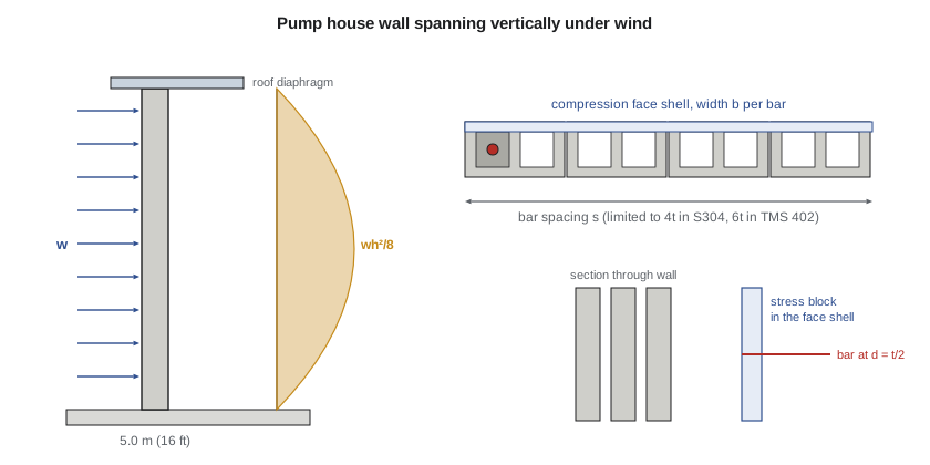
The pump house is 32 ft by 24 ft in plan with 8 in. CMU walls 16 ft high from the slab to the roof bearing. The roof is a steel deck on open-web steel joists spanning the 24 ft direction, and the deck acts as a diaphragm that supports the top of each wall. The bottom of the wall is doweled into the slab. For out-of-plane loading, each vertical strip of wall is a simply supported beam 16 ft long. The strength-level wind on the wall, combining internal and external pressure for this exposure, is 30 psf, so
Unreinforced masonry
An unreinforced wall resists bending through the modulus of rupture of the masonry normal to the bed joints, \(f_r\), which TMS 402 gives in a table by mortar type and grouting. For hollow units in Type S portland cement-lime mortar it is of the order of 84 psi, a small and variable number. The design strength is \(\phi M_n = \phi f_r S_n\) with \(\phi = 0.60\), plus a contribution from axial load, which is neglected here.
# Lesson 8: pump house wall, out-of-plane wind, 8 in. CMU, span 16 ft (TMS 402 strength design)
t, fs_t, h = 7.625, 1.25, 16.0
fm, fy = 2000.0, 60000.0              # psi
wu = 1.0 * 30.0                        # psf, strength-level wind on the wall
Mu = wu * h**2 / 8                     # lb-ft/ft
print(f"wu = {wu:.0f} psf, Mu = {Mu:.0f} lb-ft/ft")

# Unreinforced, ungrouted: face shells only, modulus of rupture normal to bed joints
y = t / 2 - fs_t / 2
I = 2 * (12 * fs_t**3 / 12 + 12 * fs_t * y**2)
S = I / (t / 2)
fr = 84.0                              # psi, hollow units, type S PCL mortar (approx.)
phiMn_urm = 0.60 * fr * S / 12
print(f"Unreinforced: S = {S:.1f} in3/ft, phi Mn = {phiMn_urm:.0f} lb-ft/ft -> {'OK' if phiMn_urm >= Mu else 'not enough'}")

d = t / 2
for bar, Ab, s in [("#4", 0.20, 32), ("#4", 0.20, 24), ("#5", 0.31, 48), ("#5", 0.31, 32)]:
    As = Ab * 12 / s
    b_eff = min(s, 6 * t)                         # compression width per bar
    a = Ab * fy / (0.80 * fm * b_eff)
    phiMn = 0.9 * As * fy * (d - a / 2) / 12
    flag = "within face shell" if a <= fs_t else "exceeds face shell"
    print(f"{bar} @ {s} in.: As = {As:.3f} in2/ft, a = {a:.2f} in. ({flag}), phi Mn = {phiMn:.0f} lb-ft/ft, Mu/phiMn = {Mu/phiMn:.2f}")

fr_g = 106.0                           # psi, partially grouted, approx. (between hollow and fully grouted)
print(f"Cracking moment with grouted cells (fr about {fr_g:.0f} psi) = {fr_g*S/12:.0f} lb-ft/ft")wu = 30 psf, Mu = 960 lb-ft/ft Unreinforced: S = 81.0 in3/ft, phi Mn = 340 lb-ft/ft -> not enough #4 @ 32 in.: As = 0.075 in2/ft, a = 0.23 in. (within face shell), phi Mn = 1247 lb-ft/ft, Mu/phiMn = 0.77 #4 @ 24 in.: As = 0.100 in2/ft, a = 0.31 in. (within face shell), phi Mn = 1645 lb-ft/ft, Mu/phiMn = 0.58 #5 @ 48 in.: As = 0.077 in2/ft, a = 0.25 in. (within face shell), phi Mn = 1285 lb-ft/ft, Mu/phiMn = 0.75 #5 @ 32 in.: As = 0.116 in2/ft, a = 0.36 in. (within face shell), phi Mn = 1899 lb-ft/ft, Mu/phiMn = 0.51 Cracking moment with grouted cells (fr about 106 psi) = 715 lb-ft/ft
The face shells give a section modulus of 81.0 in³ per foot, and the unreinforced wall resists only 340 lb·ft/ft, about a third of the 960 lb·ft/ft required. Unreinforced block walls 16 ft high are therefore limited to sheltered interior walls or lower heights; the pump house walls must be reinforced.
Worked problem
An interior partition in the wash bay
The wash bay has an interior hollow CMU partition 12 ft high between the wash area and the equipment room, braced at the top by the roof joists. Interior partitions are designed for a small lateral pressure from air pressure differences and impact, taken here as 10 psf at strength level. Can it be unreinforced?
Show solution
- \[M_u = \frac{10(12)^2}{8} = 180\ \text{lb·ft/ft} \le \phi M_n = 340\ \text{lb·ft/ft}\]
Answer: Yes, at a ratio of 0.53, and the partition is built unreinforced with joint reinforcement every second course to control shrinkage cracking. The comparison with the exterior wall shows how quickly height and pressure use up the strength of plain masonry: the moment grows with the square of the height.
Reinforced masonry in flexure
Reinforced masonry is designed on the same assumptions as reinforced concrete: plane sections remain plane, the masonry carries no tension, the steel yields, and the masonry compression is represented by an equivalent rectangular stress block. The differences are in the numbers: the masonry crushing strain, the stress block intensity and the effective width of the compression zone.
In TMS 402, the stress block has an intensity of \(0.80f'_m\) over a depth \(a = 0.80c\), and the maximum usable strain is 0.0025 for concrete masonry and 0.0035 for clay masonry. With one layer of steel at depth \(d\), equilibrium and the moment about the compression resultant give
For a bar centered in an 8 in. wall, \(d = 3.81\) in. In a partially grouted wall the compression zone is the face shell plus the grouted core, and its width per bar is limited to the bar spacing, six times the wall thickness and 72 in.; if the stress block depth \(a\) falls within the 1-1/4 in. face shell, the section acts as a rectangle of that width. If \(a\) extends past the face shell, the ungrouted cores must be allowed for, as with a T-beam.
Worked problem
Reinforcing the pump house wall
Find the design strength of the 8 in. wall with #5 bars at 32 in. centered in the wall, \(f'_m = 2000\) psi, \(f_y = 60\) ksi.
Show solution
- Per bar, with \(b = \min(32, 6 \times 7.625) = 32\) in.:
- \[a = \frac{0.31(60)}{0.80(2.0)(32)} = 0.36\ \text{in.} \le 1.25\ \text{in. (in the face shell)}\]
- Per foot, \(A_s = 0.31(12/32) = 0.116\) in²/ft:
- \[\phi M_n = 0.9(0.116)(60)\Big(3.81 - \frac{0.36}{2}\Big) = 22.8\ \text{kip·in./ft} = 1899\ \text{lb·ft/ft}\]
Answer: The wall resists 1899 lb·ft/ft against 960, a ratio of 0.51. Lighter options, #4 at 32 in. or #5 at 48 in., also work for wind alone, but the team adopts #5 at 32 in. because lesson 9 adds roof load, eccentricity and second-order moments, and because bars at 32 in. also suit the corners, the door jambs and the bond beam layout.
Limits on reinforcement
Like concrete, reinforced masonry should fail by yielding of the steel, not crushing of the masonry. TMS 402 limits the reinforcement by requiring the steel to reach a multiple of its yield strain when the masonry reaches its maximum usable strain, with the multiple depending on the seismic design category and the type of member, and it sets minimum reinforcement through prescriptive seismic requirements. The design strength must also exceed the cracking moment, so that the wall does not fail suddenly the first time it cracks; the pump house wall has \(\phi M_n = 1899\) lb·ft/ft against an estimated cracking moment of about 715 lb·ft/ft.
Bars in masonry are also limited in size relative to the cell. A bar should not exceed about one quarter of the least clear dimension of the cell, and the total steel area in a cell is limited, so there is room for the grout to flow around the bar and bond to it. Lap splices are long, often 50 to 60 bar diameters or more, because the bond strength of grout in a block cell is lower than that of concrete.
Walls spanning horizontally and in two directions
A wall supported by columns or cross walls at its ends can span horizontally, relying on tension parallel to the bed joints in unreinforced work or on horizontal joint reinforcement and bond beams in reinforced work. Walls supported on three or four edges span in two directions, and design methods based on yield line analysis allow the load to be shared between the two spans, which can make unreinforced walls workable at heights that would fail as one-way vertical spans. The pump house corners act this way near the ends of each wall, but the design conservatively treats each wall as spanning vertically.
Deflection and the control of cracking
A reinforced wall that cracks under wind becomes much more flexible, because only the steel and the compression face shell resist bending. For walls that support brittle finishes or glazing, the deflection under service wind is checked. Lesson 9 computes it with the cracked moment of inertia and shows that the pump house walls deflect only a few millimeters under service load. Horizontal cracks in the bed joints open and close with each storm; they are harmless in a reinforced wall but would admit water in an unreinforced one.
Supporting the top of the wall
The simply supported strip assumed in design needs real supports. At the bottom, dowels from the slab lap with the vertical bars and the slab resists the horizontal reaction. At the top, the wall reaction, half the wind on the wall, must pass into the roof diaphragm. For the pump house, a grouted and reinforced bond beam runs around the top of the walls, steel angles bolted to the bond beam carry the deck edge, and anchor bolts at close spacing transfer the reaction in both directions, so that suction on the wall cannot pull it away from the roof. The bond beam also acts as the diaphragm chord and ties the corners together. Many failures of masonry walls in storms start at this connection rather than in the wall itself.
Basement and retaining walls
Masonry walls below grade, such as the walls of a small pump chamber or a basement, resist soil pressure as well as the load from above. Soil pressure increases with depth, so the maximum moment is lower in the wall than for wind and the reinforcement is placed toward the tension face, the inside, for larger \(d\). Below-grade walls are usually fully grouted for water tightness and durability, and they need drainage behind them so that water pressure does not build up. The lift station below the pump house was designed in reinforced concrete in CIV-341, so the masonry starts at the slab.
Common mistakes
MistakeRelying on unreinforced masonry for tall exterior walls.
InsteadThe flexural tensile strength normal to the bed joints is small and variable; tall walls need reinforcement.
MistakeUsing the full bar spacing as the compression width without checking the limits.
InsteadLimit the width per bar to the spacing, six times the thickness and 72 in.
MistakeAssuming a rectangular section when the stress block is deeper than the face shell.
InsteadCheck \(a\) against the face shell thickness; if it is deeper, treat the section as a T.
MistakeChoosing the reinforcement for wind alone.
InsteadAdd axial load, eccentricity and second-order effects before finalizing the bars.
Summary and key terms
- Out-of-plane wind: \(M_u = w_u h^2/8\) for a wall spanning vertically; the pump house wall has \(M_u = 960\) lb·ft/ft.
- Unreinforced strength \(\phi f_r S_n\) is about 340 lb·ft/ft for a hollow 8 in. wall.
- Reinforced: \(a = A_sf_y/(0.80f'_mb)\) and \(\phi M_n = \phi A_sf_y(d - a/2)\) with \(\phi = 0.90\).
- #5 at 32 in. gives 1899 lb·ft/ft with the stress block inside the face shell.
- Reinforcement must be enough to carry the cracking moment but small enough for the steel to yield.
- Out-of-plane loading
- Load acting perpendicular to the face of a wall.
- Modulus of rupture
- fr, the tensile strength of masonry in bending, given by TMS 402 for each direction.
- Effective compression width
- The width of a partially grouted wall that acts with each bar in compression.
- Equivalent stress block
- A uniform stress over a depth a that represents the masonry compression zone.
- Cracking moment
- The moment at which the masonry first cracks in flexural tension.
- Joint reinforcement
- Wire reinforcement laid in the bed joints.
- Yield line analysis
- A method for the strength of walls and slabs spanning in two directions.
- Lap splice
- An overlap of two bars that transfers force between them by bond.
Practice problems
Work each problem on paper first, then reveal the answer to check.
Find \(\phi M_n\) for #4 bars at 24 in. in the pump house wall.
Show answer
\(A_s = 0.100\) in²/ft, \(a = 0.31\) in., \(\phi M_n = 1645\) lb·ft/ft.
How would the unreinforced resistance change if the wall spanned horizontally between cross walls?
Show answer
It would rise, because tension parallel to the bed joints is stronger, helped by the interlock of units in running bond.
Why is the bar placed at the center of the wall rather than near the inside face?
Show answer
Wind acts in both directions, so a central bar resists bending either way.
Why are lap splices in masonry longer than in concrete?
Show answer
The bond strength of grout in a block cell is lower than that of concrete.
The roof of the pump house is replaced by a heavier precast roof that no longer acts as a diaphragm. What happens to the wall design?
Show answer
The top of the wall is no longer supported, so the wall becomes a cantilever from the slab with four times the moment, and the walls would need far more reinforcement or a new roof diaphragm and bracing.
Why is joint reinforcement placed in an unreinforced partition?
Show answer
It controls the width and spacing of shrinkage cracks in the block, although it is not counted for flexural strength normal to the bed joints.
Lesson quiz · 5 questions
Score 60% or more to complete this lesson.
Create a free account to save your progress, take quizzes and earn a certificate.