
CIV-421 · Lesson 12 of 12 · 19 min
Capstone: the pavilion roof and the pump house walls
The final lesson brings the course together. Priya asks Owen to assemble the design of the training pavilion roof and the pump house walls into a single design package for review: a load summary, a member schedule with every governing check, the connection and detailing decisions, the fire and durability measures, and the drawings and specification items that will make sure the building is built as designed. The review is the last chance to catch an error before the drawings go to tender, so the team checks not only the numbers but the assumptions behind them.
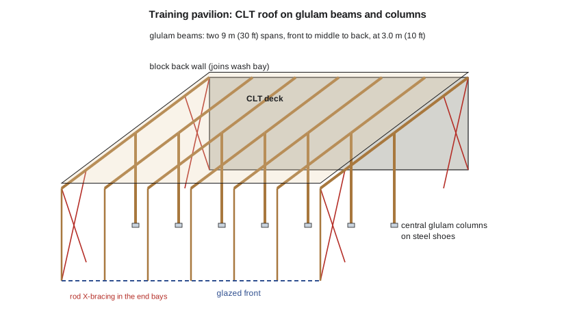
The design basis
The design basis records the codes, loads and materials, so that a reviewer can check every number against a stated assumption. For the pavilion and the pump house it lists the edition of the Minnesota State Building Code and the IBC it adopts, ASCE 7 for loads, the NDS and SDPWS for wood and TMS 402/602 for masonry, the risk category of each building (II for the pavilion, IV for the pump house, an essential facility for the wastewater system), the roof snow load of 42 psf, the wind speeds and pressures, the roof dead loads, and the materials: 24F-V4 glulam, E1 CLT, SPF No.1/No.2 lumber, \(f'_m = 2000\) psi CMU with Type S mortar, and Grade 60 bars.
Design summary
Sofia's last script collects the governing checks from every lesson into one table, so that the reviewer sees at a glance which members are close to their limits and why.
# Lesson 12: design summary for the training pavilion roof and the pump house walls (US customary)
checks = []
def add(member, check, demand, capacity, unit):
    checks.append((member, check, demand, capacity, unit))

# CLT roof panel, 3-ply 4-1/8 in., 10 ft span (lesson 4), ASD
add("CLT roof panel", "bending", 838, 5205, "lb-ft/ft")
add("CLT roof panel", "fire, 1 hour", 838, 1751, "lb-ft/ft")
# Glulam beam 6-3/4 x 21, 24F-V4, 30 ft (lessons 2 and 4), ASD
add("Glulam beam", "bending", 79.3, 101.3, "kip-ft")
add("Glulam beam", "snow deflection (L/360)", 0.82, 1.00, "in.")
add("Glulam beam", "fire, 1 hour", 79.3, 106.6, "kip-ft")
# Interior column 6-3/4 x 7-1/2, 15 ft (lesson 3), ASD
add("Interior column", "compression", 21.5, 45.6, "kips")
# Beam-to-column knife plate, six 3/4 in. bolts in two rows (lesson 5), ASD
add("Knife-plate connection", "bolts, perpendicular to grain", 10.6, 6 * 1.936, "kips")
add("Knife-plate connection", "splitting, de = 16.5 in.", 10.6, 14.0, "kips")
# Pump house wall, 8 in. CMU, #5 @ 32 in. (lessons 8 and 9), strength design
add("Pump house wall", "wind + P-delta, 1.2D + 1.0W + 0.5S", 1.08, 2.17, "kip-ft/ft")
add("Pump house wall", "wind + P-delta, 0.9D + 1.0W", 1.02, 2.05, "kip-ft/ft")
# Wash-bay shear wall, lw 24 ft (lesson 10), strength design
add("Wash-bay shear wall", "in-plane shear", 34.0, 109.5, "kips")
add("Wash-bay shear wall", "in-plane flexure", 680, 2510, "kip-ft")

print(f"{'Member':24s} {'Check':38s} {'Demand':>8s} {'Capacity':>9s}  Ratio")
for m, c, d, r, u in checks:
    print(f"{m:24s} {c:38s} {d:8.2f} {r:9.2f}  {d/r:5.2f}  {u}")
worst = max(checks, key=lambda x: x[2] / x[3])
print(f"\nHighest ratio: {worst[0]}, {worst[1]} at {worst[2]/worst[3]:.2f}")

area = 60.0 * 60.0               # seven lines of beams at 10 ft, two 30 ft spans each
clt_ft3 = area * 4.125 / 12
glulam_ft3 = 14 * 6.75 * 21.0 / 144 * 30.0
print(f"Timber volume: CLT {clt_ft3:.0f} ft3, glulam beams {glulam_ft3:.0f} ft3")
print(f"Timber weight at about 30 pcf: {(clt_ft3 + glulam_ft3) * 30 / 2000:.1f} tons")Member Check Demand Capacity Ratio CLT roof panel bending 838.00 5205.00 0.16 lb-ft/ft CLT roof panel fire, 1 hour 838.00 1751.00 0.48 lb-ft/ft Glulam beam bending 79.30 101.30 0.78 kip-ft Glulam beam snow deflection (L/360) 0.82 1.00 0.82 in. Glulam beam fire, 1 hour 79.30 106.60 0.74 kip-ft Interior column compression 21.50 45.60 0.47 kips Knife-plate connection bolts, perpendicular to grain 10.60 11.62 0.91 kips Knife-plate connection splitting, de = 16.5 in. 10.60 14.00 0.76 kips Pump house wall wind + P-delta, 1.2D + 1.0W + 0.5S 1.08 2.17 0.50 kip-ft/ft Pump house wall wind + P-delta, 0.9D + 1.0W 1.02 2.05 0.50 kip-ft/ft Wash-bay shear wall in-plane shear 34.00 109.50 0.31 kips Wash-bay shear wall in-plane flexure 680.00 2510.00 0.27 kip-ft Highest ratio: Knife-plate connection, bolts, perpendicular to grain at 0.91 Timber volume: CLT 1238 ft3, glulam beams 413 ft3 Timber weight at about 30 pcf: 24.8 tons
The highest ratio, 0.91, is the knife-plate bolts loaded across the grain, followed by the snow deflection of the glulam beams at 0.82 and their bending at 0.78: in timber, connections and stiffness, not member strength, govern. With the beam also bearing on the saddle seat, the connection has two load paths. The masonry walls are lightly stressed, at 0.50 or less, because minimum reinforcement and detailing govern a building of this size.
Member schedule
| Member | Size and grade | Governing check | Ratio |
|---|---|---|---|
| Roof deck | 4-1/8 in. 3-ply CLT, E1 | Fire, 1 hour | 0.48 |
| Roof beams (30 ft, at 10 ft) | 6-3/4 x 21 glulam, 24F-V4, cambered 1/2 in. | Snow deflection, L/360 | 0.82 |
| Interior columns (15 ft) | 6-3/4 x 7-1/2 glulam, 24F-V4 | Compression | 0.47 |
| Beam-column connection | Steel saddle, 3/8 in. knife plate, six 3/4 in. bolts | Bolts across grain | 0.91 |
| Salt shed posts (16 ft) | 5-1/8 x 10-1/2 glulam, 24F-V4 | Combined bending and compression | 0.78 |
| Annex floor joists (14 ft) | 2x10 SPF No.1/No.2 at 12 in. | Bending | 0.99 |
| Annex end walls | 15/32 in. Structural I, 8d at 6/4 in. | Shear, first story | 0.71 |
| Pump house walls (16 ft) | 8 in. CMU, #5 at 32 in. | Wind with P-delta | 0.50 |
| Wash bay end walls | 8 in. CMU, #5 at 32 in., bond beams at 48 in. | In-plane shear | 0.31 |
The review
Owen presents the package and Priya works through her review list. It is the same list she uses on every timber and masonry project, and each item corresponds to a lesson in this course.
Loads and combinations come first: are the snow load and its drifting at the step between the pavilion and the taller garage accounted for? The pavilion roof is lower than the garage roof next to it, so snow can drift against the garage wall. Owen had used the uniform snow load; the review adds a drift check on the two beams nearest the garage, which pushes their deflection over the limit. Those two beams are increased to 175x608 (6-3/4 x 24). This is the kind of error a review is meant to catch: not a mistake in arithmetic but a missing load case.
Material assumptions come next: are the service conditions right? The salt shed posts were designed with dry-service values on the strength of a protective finish and an enclosed shed. Priya asks for a moisture survey of the existing shed before the design is final, and a note on the drawings requiring the finish to be maintained, because a design that depends on a finish depends on maintenance.
Connections and details: is every connection designed for the right direction of load relative to grain, and are bolts placed so that the wood can shrink? The knife-plate connection passes, with the bolts low in the beam ends and slotted holes in the plate. The drawings must show the bolt positions exactly, because a fabricator who moves them to the middle of the beam would reduce the splitting resistance by more than half.
Fire: the pavilion meets a one-hour rating without protection, but its connections must be concealed, so the saddles are recessed into the column tops and the bolt heads plugged. Durability: the column shoes lift the end grain above the slab, the CLT roof has a continuous membrane and the glulam is wrapped until the roof is closed in. Movement: the block walls have control joints, the annex veneer has expansion joints and the shrinkage gaps are shown. Inspection: the specification calls for field review of the glulam connections, of the masonry reinforcement before each grout lift, of the shear wall nailing and of the hold-downs.
Drawings and specifications
The design is only as good as the information that reaches the site. Timber and masonry drawings carry information that steel and concrete drawings often leave to shop drawings: the grade and appearance class of each glulam member and its camber; the moisture content of lumber at delivery; the nail sizes and spacings of every shear wall and diaphragm; the type and spacing of every hold-down and tie; the unit strength, mortar type and grout of every masonry wall; the location of every control and expansion joint; and the flashing and weep details. The specification adds the quality assurance requirements: prism tests for \(f'_m\), inspection of reinforcement and grouting, and protection of materials from weather.
The engineer of record reviews the shop drawings of the glulam fabricator and the CLT manufacturer, including the connection hardware, and the contractor's erection procedure, which must include the temporary bracing of the beams until the deck is fixed. For the pump house, an essential facility, the statement of special inspections lists the masonry and connection inspections required by the IBC and TMS 402, and the special inspector reports to the building official.
During construction
The design does not end at tender. On site, the glulam and CLT arrive wrapped and are inspected for damage and moisture before erection; members with dents at the connection zones or with moisture content above the specified limit are rejected or dried. The masonry contractor builds a sample panel showing the units, mortar color, joint tooling, control joint and flashing details, and the panel becomes the standard for the work. Cold-weather procedures are reviewed before the first block is laid, because the pump house walls will go up in November. The team keeps a record of every change, such as a fabricator's request to substitute a different bolt or hanger, and checks each one against the design basis before accepting it. Finally, the as-built drawings record what was actually built, so that whoever alters the buildings in thirty years knows what they are working with.
Choosing between timber and masonry
The phase 3 buildings show where each material fits. Timber suits the pavilion, a long-span, lightweight public roof where warmth, appearance, speed of erection and low embodied carbon matter, and the salt shed, where salt would corrode steel and concrete. Masonry suits the pump house and the wash bay, small, robust buildings where impact, fire, moisture and long maintenance-free life matter more than span. Both materials demand attention to moisture, movement and connections, and both reward designers who understand how they are made and built.
The timber volume Sofia's script reports, about 46 m³ (1,650 ft³) for the pavilion roof, stores very roughly one metric ton of carbon dioxide per cubic meter, a rough rule for softwood, so about 40 metric tons (45 tons) of CO₂. The city's sustainability office will include it in its reporting, with the caveat that the full life cycle, including the steel, concrete and masonry in the rest of the project, needs a proper assessment.
Worked problem
The drift case at the garage wall
The two pavilion beams nearest the garage carry a snow drift that adds an average of 25 psf over their tributary width. Check the 6-3/4 x 21 beam and find the depth that restores span/360 under snow.
Show solution
- Snow on the beam rises from 42 to 67 psf, so the snow deflection rises in proportion:
- \[\Delta_S = 0.82\Big(\frac{67}{42}\Big) = 1.31\ \text{in.} > 1.00\ \text{in.}\]
- Deflection varies with \(1/d^3\), so the required depth is
- \[d \ge 21\Big(\frac{1.31}{1.00}\Big)^{1/3} = 23.0\ \text{in.} \to 24\ \text{in. (16 laminations)}\]
Answer: Use 6-3/4 x 24 for the two beams next to the garage, keeping the same width so the saddles and connections are unchanged. Their bending ratio rises but remains below 0.9, and the connection is rechecked for the larger reaction with eight bolts.
Common mistakes
MistakeTreating the review as an arithmetic check.
InsteadMost serious errors are missing load cases or wrong assumptions; review the basis, not only the numbers.
MistakeAssuming the fabricator will choose bolt positions.
InsteadShow connection geometry on the drawings; splitting resistance depends on it.
MistakeRelying on a finish or coating without a maintenance requirement.
InsteadState maintenance requirements wherever the design depends on them.
MistakeLeaving temporary bracing to the contractor without stating the need.
InsteadRequire it on the drawings and review the erection procedure.
Summary and key terms
- A design package has a design basis, a load summary, a member schedule with governing checks, details, and inspection requirements.
- In the pavilion, the knife-plate bolts (0.91) and beam stiffness (0.82) govern; masonry walls are lightly stressed.
- The review found a missing snow drift case, which deepened two beams; reviews catch assumptions, not arithmetic.
- Drawings for timber and masonry carry grades, cambers, nailing, hold-downs, ties, joints, flashing and quality assurance.
- Timber suits light, long-span and corrosive environments; masonry suits robust, durable small buildings; both depend on moisture, movement and connection details.
- Design basis
- The record of codes, loads, materials and assumptions on which a design rests.
- Member schedule
- A table of members with their sizes, grades and governing checks.
- Snow drift
- Accumulation of snow against a higher roof or obstruction, adding to the uniform snow load.
- Shop drawings
- Drawings prepared by the fabricator showing how members and connections will be made.
- Erection bracing
- Temporary bracing that stabilizes members until the permanent structure is complete.
- Field review
- Site observation by the engineer to confirm that work follows the design.
- Special inspection
- Inspection by a qualified inspector required by the building code for critical work.
- Embodied carbon
- The greenhouse gas emissions associated with producing and building with a material.
Practice problems
Work each problem on paper first, then reveal the answer to check.
Why was the snow drift case missed in the first design?
Show answer
The beams were designed for the uniform roof snow load only; the lower pavilion roof beside the taller garage creates a drift case that must be added.
What happens to the interior column load next to the garage when the drift is added?
Show answer
It rises by roughly the drift load on its 270 ft² tributary area, about 6.8 kips, and the 6-3/4 x 7-1/2 column still works at about 0.62.
List three things on the drawings that are specific to timber.
Show answer
Glulam grade and camber, connection geometry and bolt positions, and lumber moisture content at delivery; also shear wall nailing and hold-downs.
Why does a design that relies on a protective finish need a maintenance note?
Show answer
The design assumption only holds as long as the finish is maintained.
Lesson quiz · 5 questions
Score 60% or more to complete this lesson.
Create a free account to save your progress, take quizzes and earn a certificate.