
CIV-421 · Lesson 6 of 12 · 19 min
Wood shear walls and diaphragms
Wind and earthquake loads push sideways on buildings, and in a wood-frame building the lateral load path runs through sheathed floors, roofs and walls. The roof and floors act as diaphragms, deep horizontal beams that collect the lateral load and deliver it to the walls. The walls parallel to the load act as shear walls, vertical cantilevers that carry it down to the foundation. Both are made of ordinary wood structural panels, plywood or oriented strand board (OSB), nailed to the framing, and their strength comes almost entirely from the nails. This lesson designs the lateral system of the two-story office annex.
The load path
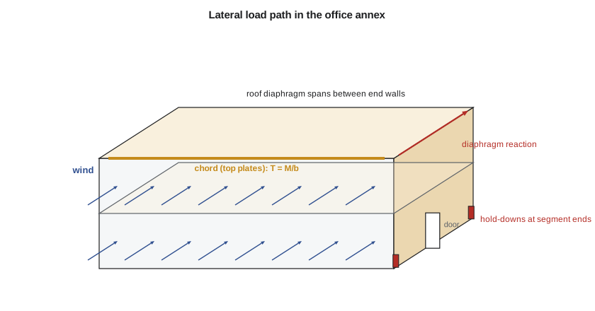
Wind on the long face of the annex pushes on the wall studs, which span from floor to floor and deliver half of their load to each diaphragm. The roof and second floor diaphragms span between the end walls, like simply supported beams lying flat. Each diaphragm delivers its end reaction to the end walls as a shear along their tops. The end walls carry the shear down through each story, overturning tries to lift one end of each wall segment, and hold-downs at the ends of the segments carry that uplift into the foundation. Every link in the chain, from the wall studs to the anchor bolts, must be designed.
Diaphragms
A diaphragm behaves like a deep I-beam. The sheathing is the web and carries shear; the boundary members at the edges perpendicular to the load, usually the double top plates of the walls or a rim joist, are the flanges or chords, and carry the bending moment as tension and compression. For a simply supported diaphragm of span \(L\) and depth \(b\) under a uniform line load \(w\):
Here \(v\) is the unit shear along the supported edges, in force per unit length, and \(T\) and \(C\) are the chord forces. The chord must be continuous over the full length, so splices in the top plates are nailed or strapped to carry \(T\). Diaphragms are designed as blocked or unblocked: blocking under every panel edge lets the nails at those edges carry shear and roughly doubles the capacity. Openings for stairs and skylights interrupt the web and need collectors and extra chords around them.
Shear walls
A shear wall is a vertical cantilever. The sheathing nailed to studs and plates carries the shear, the end studs (chords) carry the overturning tension and compression, and the hold-downs anchor the tension chord. Only full-height segments, without openings, are counted in the simple segmented method, and each segment must have an aspect ratio of height to length within the limits of the standard, typically 3.5 to 1 for wind with a reduction above 2 to 1. Other methods, such as the perforated shear wall method and force transfer around openings, count more of the wall with extra detailing.
In the United States, shear walls and diaphragms are designed by the Special Design Provisions for Wind and Seismic (SDPWS), a companion standard to the NDS. It tabulates nominal unit shear capacities for combinations of sheathing, nails and spacing, separately for wind (\(v_w\)) and seismic (\(v_s\)) loading. The allowable unit shear in ASD is the nominal value divided by 2.0, and the LRFD design value is the nominal value times \(\phi_D = 0.80\). Values for 15/32 in. Structural I sheathing with 8d common nails, for wind, are about 730, 1065, 1370 and 1790 plf at edge nail spacings of 6, 4, 3 and 2 in. Sheathing both faces roughly doubles the capacity.
The unit shear in a wall line is the shear delivered by the diaphragm divided by the total length of full-height segments. A segment's overturning moment at its base is the sum of each story shear times its height above the base, and the hold-down force is
where \(l_s\) is the segment length and \(D_s\) the dead load on the segment. Strictly the moment arm is the distance between the chord centerlines, slightly less than the segment length, and designers allow for it.
Wind on the office annex
The annex is 52 ft long, 26 ft wide and two stories of 10 ft. With wind on the 52 ft face, the ASD (0.6W) line loads delivered to the diaphragms are 125 plf at the roof and 180 plf at the second floor, from the wind pressure on the wall area tributary to each level. Each end wall is 26 ft long. In the second story it has no full-height openings; in the first story, a 5 ft door in the middle leaves two 10-1/2 ft full-height segments. The sheathing is 15/32 in. Structural I with 8d common nails.
# Lesson 6: wind on the two-story office annex, 52 ft x 26 ft, story height 10 ft (SDPWS, ASD)
L, B, h = 52.0, 26.0, 10.0
w_roof, w_floor = 0.125, 0.18         # ASD (0.6W) wind line loads on the diaphragms (kip/ft)
for name, w in [("roof", w_roof), ("second floor", w_floor)]:
    R = w * L / 2
    v = R / B * 1000
    T = w * L**2 / 8 / B
    print(f"{name:12s}: reaction {R:.2f} kips, unit shear {v:.0f} plf, chord force {T:.2f} kips")

V2 = w_roof * L / 2
V1 = V2 + w_floor * L / 2
seg2, seg1 = [26.0], [10.5, 10.5]      # full-height segments (first story has a 5 ft door)
v2, v1 = V2 / sum(seg2) * 1000, V1 / sum(seg1) * 1000
print(f"\nEnd wall shear: second story {V2:.2f} kips -> {v2:.0f} plf; first story {V1:.2f} kips -> {v1:.0f} plf")

# 15/32 in. Structural I sheathing, 8d common nails: nominal wind unit shear (plf) by edge spacing
vw = {6: 730, 4: 1065, 3: 1370, 2: 1790}
for name, v in [("second story", v2), ("first story", v1)]:
    ok = [s for s, x in vw.items() if x / 2.0 >= v]
    if ok:
        s = max(ok); print(f"{name}: v = {v:.0f} plf, one side, nails at {s} in. (allowable {vw[s]/2:.0f} plf)")
    else:
        s = max(s for s, x in vw.items() if x >= v)
        print(f"{name}: v = {v:.0f} plf, both sides, nails at {s} in. (allowable {vw[s]:.0f} plf)")

# Hold-down at the end of a 10.5 ft first-story segment, ASD 0.6D resisting
lseg = 10.5
Vseg1 = V1 * lseg / sum(seg1)
Vseg2 = V2 * lseg / sum(seg2)
M = Vseg2 * 2 * h + (Vseg1 - Vseg2) * h
Dres = 0.6 * 0.31 * lseg            # 0.6 x dead load on the segment (0.31 kip/ft)
T = M / lseg - Dres / 2
print(f"\nSegment {lseg} ft: overturning {M:.1f} kip-ft, hold-down tension = {M/lseg:.2f} - {Dres/2:.2f} = {T:.2f} kips")roof : reaction 3.25 kips, unit shear 125 plf, chord force 1.62 kips second floor: reaction 4.68 kips, unit shear 180 plf, chord force 2.34 kips End wall shear: second story 3.25 kips -> 125 plf; first story 7.93 kips -> 378 plf second story: v = 125 plf, one side, nails at 6 in. (allowable 365 plf) first story: v = 378 plf, one side, nails at 4 in. (allowable 532 plf) Segment 10.5 ft: overturning 52.8 kip-ft, hold-down tension = 5.03 - 0.98 = 4.05 kips
Worked problem
End wall design
Design the end walls of the annex: find the unit shear in each story, choose the nail spacing for one layer of 15/32 in. Structural I, and find the hold-down force at a first-story segment with a dead load of 310 plf.
Show solution
- Second story: \(V_2 = 0.125(52)/2 = 3.25\) kips over 26 ft:
- \[v_2 = 125\ \text{plf} \le \frac{730}{2.0} = 365\ \text{plf at 6 in.}\]
- First story: \(V_1 = 3.25 + 0.18(52)/2 = 7.93\) kips over two 10.5 ft segments:
- \[v_1 = \frac{7930}{21} = 378\ \text{plf} \le \frac{1065}{2.0} = 532\ \text{plf at 4 in.}\]
- Hold-down at a 10.5 ft segment: the segment takes 1.31 kips from the roof level (at 20 ft) and 2.65 kips from the second floor (at 10 ft):
- \[M = 1.31(20) + 2.65(10) = 52.8\ \text{kip·ft} \qquad T = \frac{52.8}{10.5} - \frac{0.6(0.31)(10.5)}{2} = 4.05\ \text{kips}\]
Answer: Use 6 in. edge nailing in the second story and 4 in. in the first, with 12 in. in the field, all edges blocked. The first-story hold-downs must resist about 4.1 kips, which calls for a manufactured hold-down with an anchor rod into the foundation and a multi-stud chord, and the second story needs a strap or rod tie through the floor. The diaphragms carry 125 and 180 plf and chord forces of 1.6 and 2.3 kips.
The door in the first story is what drives the design: it removes a fifth of the wall length where the shear is largest, so the first-story unit shear is three times that of the second story. Moving the door to the end of the wall would leave one longer segment and reduce both the unit shear and the hold-down force, a good example of how architecture and structure interact in wood buildings.
Anchorage and sliding
The shear at the base of each wall must pass into the foundation. Anchor bolts through the sill plate carry it in bearing on the wood, so they are designed as bolted connections loaded parallel to grain, with plate washers that keep the sill from splitting and that hold the plate down against the uplift of the sheathing. Their spacing follows from the unit shear and the capacity of one bolt, and the first and last bolts sit close to the ends of each sill piece. At the second floor, the shear passes from the upper wall into the floor framing through nails in the bottom plate and from the floor into the wall below through blocking or rim joists. Each transfer is checked, because a wall that is strong in itself but poorly attached to what is below it does nothing.
Deflection of shear walls and diaphragms
Shear walls deflect through four mechanisms: bending of the wall as a cantilever, shear deformation of the panels, slip of the nails, and stretching and slip of the hold-down. For typical walls the nail slip and hold-down slip dominate, which is why the standards include deflection equations with a nail slip term and why tight-fitting hold-downs and shrinkage compensating devices matter in multi-story buildings. Story drift limits under wind protect cladding and partitions; under earthquake they protect the structure itself.
Earthquake design
Thunder Bay and Duluth have low seismic hazard, and wind governs the annex. Where earthquake governs, wood shear walls are among the most ductile lateral systems available, because the many nails yield progressively and dissipate energy. ASCE 7 assigns light-frame wood walls with wood structural panels a response modification coefficient \(R = 6.5\), and SDPWS seismic values are lower than wind values to keep the walls in a controlled range of behavior under cyclic load.
Mass timber lateral systems
The pavilion has no wood-frame walls. Its CLT roof is the diaphragm, with screwed splines at the panel joints carrying shear and the edge glulam beams acting as chords, and the lateral load goes to steel rod X-bracing in two end bays and to the concrete block wall at the back of the pavilion, which joins the wash bay. For taller mass timber buildings, CLT shear walls, rocking walls with hold-downs, braced frames and concrete cores are all used, each with its own design rules.
Details that make the system work
Lateral systems in wood fail at their weakest link, and the weakest link is rarely the sheathing. Common problems are missing or under-nailed blocking at panel edges, top plate splices that cannot carry the chord force, hold-downs installed loosely or omitted, anchor bolts too close to the ends of sill plates, and penetrations cut through shear walls by other trades. Inspection during construction, especially of nail spacing and hold-down installation, is part of the design. Over-driven nails, which break the surface of the sheathing, reduce capacity markedly, so pneumatic nailers must be adjusted.
Common mistakes
MistakeCounting the full wall length, including openings, as shear wall.
InsteadIn the segmented method only full-height segments resist shear; openings reduce the effective length.
MistakeForgetting chord forces in the diaphragm.
InsteadChords carry \(M/b\) in tension and compression; top plate splices must be designed for it.
MistakeOmitting the hold-down or tie at upper stories.
InsteadOverturning of upper stories must be carried down through the floor by straps or rods to the hold-downs below.
MistakeIgnoring nail spacing on site.
InsteadShear wall capacity depends directly on edge nail spacing; inspect it.
Summary and key terms
- Diaphragms span between shear walls like deep beams: \(v = R/b\) in the sheathing and \(T = M/b\) in the chords.
- Shear walls: SDPWS nominal unit shears, divided by 2.0 for ASD or multiplied by 0.80 for LRFD; only full-height segments count.
- Hold-down force: overturning moment over segment length, less the resisting dead load.
- Annex end walls: 125 plf in the second story (6 in. nailing) and 378 plf in the first (4 in. nailing), hold-down 4.1 kips.
- The weakest link is often a detail: blocking, splices, hold-downs and anchorage.
- Diaphragm
- A horizontal structural element, such as a sheathed floor or roof, that carries lateral load to the walls.
- Shear wall
- A wall designed to resist lateral load in its own plane.
- Chord
- A boundary member of a diaphragm or shear wall that carries tension or compression from bending.
- Unit shear
- Shear force per unit length along a diaphragm edge or shear wall.
- Hold-down
- A device that anchors the tension chord of a shear wall segment to the structure below.
- Blocking
- Framing installed under unsupported panel edges so they can be nailed.
- Collector
- A member that gathers diaphragm shear and delivers it to a shear wall.
- Segmented shear wall
- A design method that counts only full-height wall segments without openings.
Practice problems
Work each problem on paper first, then reveal the answer to check.
If the annex door moved to the end of the wall, leaving one 21 ft segment, what would the first-story unit shear be?
Show answer
The same 378 plf, because the total segment length is unchanged, but there would be one hold-down pair instead of two, and each would see a smaller force because of the longer lever arm.
What happens to the diaphragm chord force if the annex were 12 m (40 ft) wide instead of 8 m (26 ft)?
Show answer
It falls in proportion: \(T = wL^2/(8b)\), so a wider diaphragm has smaller chord forces.
Find the allowable unit shear of a wall sheathed on both faces with nails at 4 in.
Show answer
\(2(1065)/2.0 = 1065\) plf, subject to the standard's limits on double-sided walls.
Why are seismic unit shear values lower than wind values?
Show answer
Cyclic earthquake loading degrades nailed connections more than wind, so a controlled, lower value is used.
Lesson quiz · 5 questions
Score 60% or more to complete this lesson.
Create a free account to save your progress, take quizzes and earn a certificate.