
CIV-421 · Lesson 11 of 12 · 20 min
Masonry details, movement joints and veneers
Most problems with masonry buildings are not structural failures but cracks, leaks, spalling and stains, and almost all of them trace back to details: movement that was not allowed for, water that was not drained, ties that corroded or were never installed. In a cold climate like that of Thunder Bay and Duluth, where walls see temperature swings of almost 100 °C (170 °F) between a winter night and a sunny summer afternoon and go through dozens of freeze-thaw cycles a year, the details decide how long a masonry wall lasts. This lesson covers movement joints, veneer walls and the durability details for the garage, the wash bay and the brick veneer on the office annex.
Why masonry moves
Masonry walls change size for several reasons at once. Temperature changes cause reversible expansion and contraction, with coefficients of about \(6.5 \times 10^{-6}\) per °C (\(3.6 \times 10^{-6}\) per °F) for clay brick and about \(9 \times 10^{-6}\) per °C (\(5 \times 10^{-6}\) per °F) for concrete block. Concrete block also shrinks permanently as it dries after manufacture and carbonates over the years. Clay brick does the opposite: fresh from the kiln it is bone dry, and it expands slowly and permanently as it takes up moisture from the air, most of it in the first months. Wood framing behind a veneer shrinks as it dries, as lesson 1 showed. Steel and concrete frames shorten under creep and shrinkage.
Restrained movement produces stress. A long block wall fixed to its footing tries to shrink but cannot slide, so it cracks, typically in a stepped pattern through the joints or straight through the units near openings. A brick veneer that expands against a concrete frame or a corner bows outward, cracks at the corner or pushes out the sealant. The cure is not to stop the movement but to divide the wall into panels that can move freely, with joints where the movement concentrates.
Control joints in concrete masonry
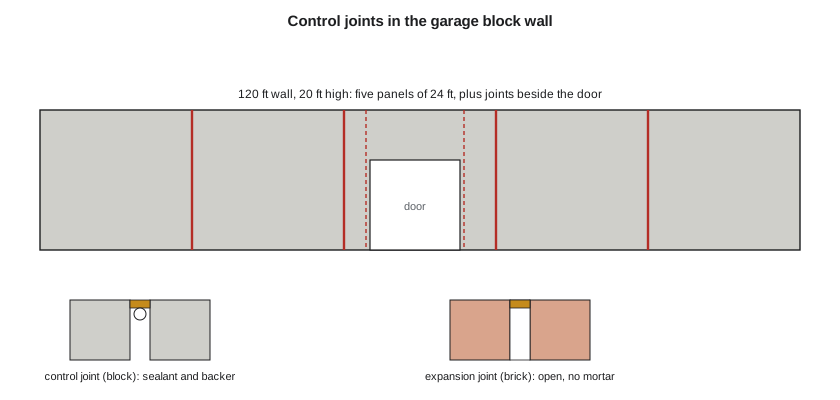
Control joints are vertical separations in concrete block walls that let the panels between them shrink without cracking. They are continuous through the height of the wall, filled with a sealant on the outside and a backer, and usually interrupt joint reinforcement but not bond beam bars, so that the wall still acts as a diaphragm and transfers shear across the joint with keyed units or a shear key. They are placed at changes in wall height or thickness, at openings, at intersections with other walls and at regular spacing along long walls.
A common guide limits the spacing of control joints in concrete masonry to 1.5 times the wall height and to about 7.5 m (25 ft), with closer spacing where the wall has little horizontal reinforcement. Horizontal joint reinforcement or bond beams allow longer panels by distributing the shrinkage into many fine cracks.
Expansion joints in clay brick
Clay brick veneer needs expansion joints rather than control joints, because it grows. They are open joints, without mortar, filled with a compressible backer and sealant, placed near corners, at changes in wall direction, at openings and along long walls. A brick expansion joint must never be filled with mortar, which would turn it into a solid joint and defeat its purpose. Typical spacings are 6 to 9 m (20 to 30 ft), with a joint within a few feet of each outside corner, because a corner lets expanding walls on both faces push against each other.
The width of the joint must allow the movement without overstressing the sealant. A sealant with a movement capability of plus or minus 25 percent can accommodate a movement of a quarter of the joint width; one rated at 50 percent, half. The joint width is therefore at least the expected movement divided by the movement capability, plus an allowance for construction tolerance.
# Lesson 11: movement in the garage CMU wall and the office annex brick veneer (US customary)
L_cmu, H = 120.0, 20.0           # ft
shrink = 0.00035                 # long-term drying shrinkage of concrete masonry (approx.)
alpha_c = 5.0e-6                 # per deg F
dT_c = 80.0
tot = L_cmu * 12 * (shrink + alpha_c * dT_c)
print(f"CMU wall: shortening if unjointed = {tot:.2f} in. over {L_cmu:.0f} ft")
s_max = min(1.5 * H, 25.0)       # common control joint spacing rule (1.5 x height, 25 ft maximum)
n = int(L_cmu // s_max) + (1 if L_cmu % s_max else 0)
print(f"Control joints: spacing limit {s_max:.0f} ft -> {n} panels of {L_cmu/n:.0f} ft, opening per joint {tot/n:.2f} in.")

L_br = 52.0
alpha_b = 3.6e-6                 # per deg F, clay brick
dT_b = 170.0                     # -30 F winter night to +140 F dark wall in sun
moist = 0.0003                   # irreversible moisture expansion of new clay brick (approx.)
for spacing in (20.0, 26.0, 52.0):
    mv = spacing * 12 * (alpha_b * dT_b + moist)
    for cap in (0.25, 0.50):
        print(f"Brick panel {spacing:4.0f} ft: movement {mv:.2f} in., sealant +/-{cap*100:.0f} % -> joint width {mv/cap:.2f} in.")

wood = 0.52
print(f"\nTwo stories of wood framing shrink about {wood:.2f} in.; brick does not. "
      f"Leave at least {wood + 0.13:.2f} in. (say 3/4 in.) under sills and at the soffit, sealed with a flexible joint.")

area = 52.0 * 20.0
a_tie = 16 / 12 * 24 / 12        # ties at 16 in. vertically and 24 in. horizontally
print(f"Ties for {area:.0f} ft2 of veneer at one per {a_tie:.2f} ft2: {area/a_tie:.0f} ties "
f"(the prescriptive maximum is one per 2.67 ft2 for wire ties), plus extra ties near openings")CMU wall: shortening if unjointed = 1.08 in. over 120 ft Control joints: spacing limit 25 ft -> 5 panels of 24 ft, opening per joint 0.22 in. Brick panel 20 ft: movement 0.22 in., sealant +/-25 % -> joint width 0.88 in. Brick panel 20 ft: movement 0.22 in., sealant +/-50 % -> joint width 0.44 in. Brick panel 26 ft: movement 0.28 in., sealant +/-25 % -> joint width 1.14 in. Brick panel 26 ft: movement 0.28 in., sealant +/-50 % -> joint width 0.57 in. Brick panel 52 ft: movement 0.57 in., sealant +/-25 % -> joint width 2.28 in. Brick panel 52 ft: movement 0.57 in., sealant +/-50 % -> joint width 1.14 in. Two stories of wood framing shrink about 0.52 in.; brick does not. Leave at least 0.65 in. (say 3/4 in.) under sills and at the soffit, sealed with a flexible joint. Ties for 1040 ft2 of veneer at one per 2.67 ft2: 390 ties (the prescriptive maximum is one per 2.67 ft2 for wire ties), plus extra ties near openings
Worked problem
Movement joints for the garage and the annex
The 120 ft east wall of the garage is 20 ft high, in 8 in. CMU. The annex is clad on its 52 ft long face in clay brick veneer. Lay out the control joints in the block wall and size the brick expansion joints.
Show solution
- Block wall: shrinkage of about 0.035 percent plus an 80 °F drop gives
- \[\Delta = 1440(0.00035 + 5 \times 10^{-6} \times 80) = 1.08\ \text{in.}\]
- Spacing limit \(\min(1.5 \times 20, 25) = 25\) ft, so five panels of 24 ft, each joint opening about 0.22 in.
- Brick: a 170 °F range plus 0.03 percent moisture expansion over 26 ft:
- \[\Delta = 312(3.6 \times 10^{-6} \times 170 + 0.0003) = 0.28\ \text{in.} \qquad w = \frac{0.28}{0.50} = 0.57\ \text{in.}\]
Answer: The garage wall gets control joints at 24 ft, aligned with the steel columns behind it so that each panel is laterally supported at its ends, plus a joint at each side of the overhead door. The annex veneer gets an expansion joint at each corner and one at mid-length, 26 ft apart, 5/8 in. wide with a sealant rated for plus or minus 50 percent. Using the full temperature range is conservative, because the sealant is installed at an intermediate temperature and sees only part of the range in each direction.
Veneer walls
A masonry veneer is a single wythe of brick or stone that is not loadbearing; it carries only its own weight and transfers the wind on it through ties to a backup wall of wood studs, steel studs, concrete or block. A cavity between the veneer and the backup, typically 1 in. or more clear and up to 4-1/2 in. or so for prescriptive designs, drains water that penetrates the veneer, and the veneer is supported at its base on a foundation ledge or a steel shelf angle. TMS 402 Chapter 13 gives prescriptive requirements for anchored veneer, including tie types, spacing and the area of wall each tie may serve.
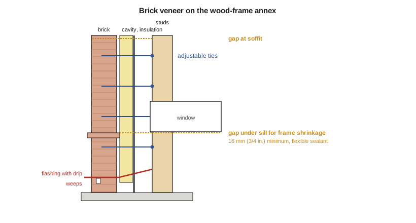
Ties must be strong enough to carry the wind on the veneer, stiff enough to keep it from cracking, and flexible in the vertical direction so that the veneer and the backup can move relative to each other. Adjustable two-piece ties do this, with a part fixed to the backup and a pintle or hook that engages it and is embedded in the mortar of the veneer. They are made of hot-dip galvanized or stainless steel, because a corroded tie behind a sound-looking veneer is one of the most dangerous hidden defects in a building; stainless steel is increasingly specified for exactly that reason.
For the annex, the ties are fixed to the studs at 600 mm (24 in.) horizontally and 400 mm (16 in.) vertically, with extra ties around each opening. Sofia's script counts about 400 of them on the long wall alone: a reminder that veneer is a system of hundreds of small connections, each of which must be installed correctly.
Wood frame and brick veneer
The annex shows a classic detailing problem. Two stories of platform framing shrink about 1/2 in. as the lumber dries, while the brick veneer expands slightly. Wherever the frame and the veneer meet in a way that cannot move, something gives. Window frames attached to the studs drop relative to the brick sill below them, so a gap of at least 3/4 in. is left under each sill, closed with a flexible sealant. At the top of the wall, the roof framing comes down while the brick stays up, so the soffit is detailed with a gap above the last course. Ties must accommodate the movement too, which is why they are adjustable.
Water management
No masonry veneer is waterproof; rain driven by wind passes through the mortar joints and the units. The design assumes this and provides a drainage plane behind the veneer: a cavity kept clear of mortar droppings, a water-resistive barrier on the backup, through-wall flashing at the base of the cavity and over every opening, with end dams at its ends, and weep holes or vents at regular spacing just above the flashing to let the water out. Flashings must extend past the face of the veneer with a drip, because flashing that stops behind the face sends water into the wall below.
For block walls without a veneer, such as the pump house and the wash bay, single-wythe walls rely on low-absorption units, well-tooled concave joints, water repellents added to the block and mortar, and flashing at the base, at bond beams and over openings. They remain more vulnerable to leaks than cavity walls, which is acceptable for an equipment building but would not be for an office.
Cold-climate durability
Freeze-thaw damage happens when water saturates a unit and then freezes, expanding and breaking off the face in a process called spalling. It is worst where masonry stays wet: at grade, at parapets and copings, under leaking sills and where de-icing salt splashes from roads and walkways. Resistance depends on the units, so the specifications call for brick and block graded for severe weathering and freeze-thaw exposure, and on the details that keep the wall from staying wet. Copings with drips and slope, sills that project, and a base course of denser units at the driveway all help. Salt is particularly damaging, because salt crystals growing in the pores add their own pressure and keep the masonry wetter.
Efflorescence, the white bloom that appears on new masonry, is salt carried to the surface by water and left behind as the water evaporates. It is harmless in itself, but it is a sign that water is moving through the wall. Persistent efflorescence points to a detail that is letting water in.
Shelf angles and lintels in veneer
In taller buildings, the veneer cannot be stacked from the foundation all the way up, so steel shelf angles fixed to the structure carry it at each floor or every few floors. A horizontal movement joint, a soft joint with sealant instead of mortar, must be left under each shelf angle, because the frame shortens and the brick grows; without it, the brick above bears on the brick below and the veneer cracks or bows. Over openings in the veneer, loose steel lintels, galvanized and with flashing over them, carry the brick above.
Common mistakes
MistakeFilling a brick expansion joint with mortar.
InsteadExpansion joints must be open, with a compressible filler and sealant, or the brick cannot expand.
MistakeOmitting control joints in long block walls.
InsteadDivide walls into panels about 1.5 times their height and no more than about 7.5 m (25 ft) long.
MistakeFixing windows rigidly between a shrinking wood frame and brick veneer.
InsteadLeave a gap under sills and at the soffit for the frame shrinkage, sealed with a flexible joint.
MistakeStopping the flashing behind the face of the veneer.
InsteadExtend flashing past the face with a drip, provide end dams and keep weeps clear.
Summary and key terms
- Concrete block shrinks and clay brick expands; temperature, moisture and frame shrinkage all move walls.
- Control joints in CMU at about 1.5 times the height and no more than 25 ft; expansion joints in brick at 20 to 30 ft and near corners.
- Joint width is the movement divided by the sealant movement capability, plus tolerance.
- Veneers drain: clear cavity, water-resistive barrier, flashing with end dams and drips, and weeps; ties are corrosion-resistant and adjustable.
- The annex veneer needs a 3/4 in. gap under sills for 1/2 in. of wood frame shrinkage.
- Control joint
- A vertical joint in concrete masonry that lets it shrink without uncontrolled cracking.
- Expansion joint
- An open joint in clay masonry that lets it expand.
- Veneer
- A non-loadbearing wythe of masonry tied to a backup wall.
- Tie
- A metal connector that carries lateral load from a veneer to its backup.
- Through-wall flashing
- A membrane that directs water in the cavity out through the veneer.
- Weep hole
- An opening at the base of a veneer that drains the cavity.
- Efflorescence
- A white deposit of salts left on masonry by evaporating water.
- Shelf angle
- A steel angle that supports a veneer at a floor level.
Practice problems
Work each problem on paper first, then reveal the answer to check.
How wide should a brick expansion joint be for 20 ft spacing with a sealant rated at plus or minus 25 percent?
Show answer
Movement 0.22 in., so at least 0.88 in.; a sealant rated at 50 percent would allow 0.44 in.
Why are control joints placed beside openings in block walls?
Show answer
Openings concentrate shrinkage stress at their corners, where cracks would otherwise start.
Why is a horizontal soft joint left under a shelf angle?
Show answer
The frame shortens and the brick grows; without the gap the brick above would bear on the brick below.
Why are stainless steel ties increasingly specified?
Show answer
A corroded tie hidden behind the veneer can let the veneer fall, and stainless steel lasts as long as the wall.
Lesson quiz · 5 questions
Score 60% or more to complete this lesson.
Create a free account to save your progress, take quizzes and earn a certificate.