
CHE-280 · Lesson 12 of 12 · 23 min
Cathodic protection, inspection and corrosion management
The final lesson brings the course together. Theo's term ends with a report to the plant manager on the state of the Kingfisher Bioenergy plant's equipment and a plan for keeping it fit for service. That plan rests on three things this lesson covers: cathodic protection for buried and submerged steel, inspection methods that find damage before it causes failure, and a corrosion management system that decides what to inspect, when, and what to do with the results. The lesson ends with Theo's capstone: a corrosion review of the plant's three highest-risk systems.
Cathodic protection
Cathodic protection (CP) prevents corrosion of a metal by making it the cathode of an electrochemical cell. Lesson 6 showed why it works: if electrons are supplied to the metal from outside, its potential is pushed down, the anodic dissolution reaction slows, and at a low enough potential the metal reaches the immunity region of its Pourbaix diagram. In practice, the metal is polarized enough to make corrosion negligible, not to reach full immunity. CP is used for buried pipelines and tanks, tank bottoms on soil, water tank interiors, ship hulls, offshore structures and reinforcing steel in concrete. It works only where the metal is in contact with an electrolyte such as soil or water; it does nothing for atmospheric corrosion or the inside of a dry pipe.
There are two types. Galvanic (sacrificial anode) systems connect the steel to a more active metal, usually magnesium in soil, or zinc and aluminum alloys in seawater; the anode corrodes and supplies the protective current, and it must be replaced when it is used up. Galvanic systems are simple, need no power and suit small structures, well-coated pipelines and low-resistivity soils. Impressed current systems use a direct current power source, a transformer-rectifier, to drive current from long-lasting anodes (high-silicon cast iron, mixed metal oxide on titanium, graphite) through the soil to the structure. They can deliver much more current and suit large or poorly coated structures and high-resistivity soils, but they need power, adjustment and monitoring, and a wrongly connected rectifier will corrode the structure rapidly instead of protecting it.
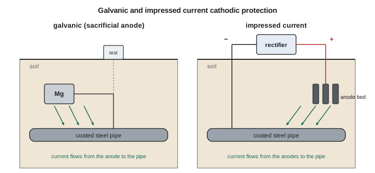
Coatings and CP work together. The coating protects most of the surface, and CP protects the steel at holidays and damage. Because CP current is needed only at the bare steel, a good coating cuts the current requirement dramatically, from amperes to tens of milliamperes for the same line. Design current densities for bare steel in soil are typically 10 to 30 mA/m\(^2\), depending on the soil, temperature and oxygen. The program at the end of this section estimates the current needed for the plant's buried firewater main at three levels of coating effectiveness, and the magnesium needed for a 25-year galvanic system.
Protection is checked by measuring the structure's potential against a reference electrode placed on the soil above it, usually a copper-copper sulfate electrode. Widely used criteria in the industry standards from AMPP for buried steel include a polarized potential of \(-850\) mV or more negative against copper-copper sulfate, or at least 100 mV of cathodic polarization. Measurements must correct for the voltage drop in the soil caused by the protection current, usually by briefly switching the current off and reading the instant-off potential. Too much protection can also cause harm: very negative potentials can disbond coatings and, on high-strength steels, cause hydrogen embrittlement.
Buried pipelines are regulated. The plant's natural gas lateral, which runs from the utility's line to the plant's meter station, falls under 49 CFR Part 192, the federal gas pipeline safety rules administered by the Pipeline and Hazardous Materials Safety Administration (PHMSA) with the state. Those rules require the line to be coated and cathodically protected, with test stations along the route, potential surveys at set intervals, rectifier checks where impressed current is used, and records kept for the life of the line. Stray current is a particular concern: direct current from nearby electric railways, other pipelines' CP systems or welding equipment can enter a pipeline in one place and leave in another, causing rapid corrosion where it leaves. Rafael's firewater main is not regulated in the same way, but he applies the same principles to it.
# Cathodic protection current and anode mass for a buried firewater line
import math
D, L = 0.2191, 450.0        # pipe outside diameter (m) and length (m)
area = math.pi * D * L
for coat_eff in (0.0, 0.95, 0.99):
    bare = area * (1 - coat_eff)
    I = bare * 0.020            # A, at 20 mA/m2 design current density for bare steel in soil
    print(f"coating {coat_eff * 100:3.0f} % effective: bare area {bare:6.1f} m2, current {I:6.2f} A")

# Magnesium anode mass for 25 years at the 99 % coating case
I = area * 0.01 * 0.020
cap = 1230                  # Ah/kg practical capacity of magnesium (approximate)
util = 0.85
mass = I * 25 * 8760 / (cap * util)
print(f"magnesium needed for 25 years = {mass:.0f} kg")

# Remaining life and next inspection for a corroded pipe spool (API 570 style)
t_act, t_req, rate = 6.10, 3.20, 0.18     # mm, mm, mm/y
rl = (t_act - t_req) / rate
print(f"remaining life = {rl:.1f} y; next thickness inspection within {min(rl / 2, 10):.1f} y")coating 0 % effective: bare area 309.7 m2, current 6.19 A coating 95 % effective: bare area 15.5 m2, current 0.31 A coating 99 % effective: bare area 3.1 m2, current 0.06 A magnesium needed for 25 years = 13 kg remaining life = 16.1 y; next thickness inspection within 8.1 y
Bare, the firewater main would need over 6 A. With a 99 percent effective coating, it needs about 60 mA, which a modest galvanic system of magnesium anodes can supply for decades. In practice, the number of anodes is set by how much current each can push through the soil, which depends on soil resistivity, and by spreading the current along the line, so the real system has more anode metal than the minimum mass. The last part of the program anticipates the inspection section below.
Inspection methods
Inspection finds and measures damage so that its effect on fitness for service can be judged. The methods are grouped as non-destructive testing (NDT), and each suits particular damage. Visual inspection is the first and most important method, internal and external, looking for corrosion, deposits, coating breakdown, leaks, distortion and cracks. Ultrasonic thickness measurement sends a sound pulse through the wall and times its echo; spot readings at fixed condition monitoring locations, repeated over years, give corrosion rates. Ultrasonic scanning maps thickness over an area to find local thinning. Radiography, including profile radiography through insulation, shows wall loss and pitting in pipe. Magnetic particle testing finds surface cracks in ferromagnetic steels; dye penetrant testing finds surface-breaking cracks in any non-porous material. Eddy current testing finds pits and cracks in heat exchanger tubes and thin non-magnetic materials; the plant uses it on the evaporator tubes. Advanced ultrasonic methods, such as phased array and time-of-flight diffraction, find and size cracks inside welds.
| Damage mechanism | Suitable inspection methods |
|---|---|
| Uniform thinning | Ultrasonic thickness at condition monitoring locations, radiography |
| Localized thinning and pitting | Ultrasonic scanning, profile radiography, eddy current for tubes, visual |
| Corrosion under insulation | Visual of jacketing, insulation removal, profile radiography, pulsed eddy current, guided waves |
| Surface cracking (SCC, fatigue) | Wet fluorescent magnetic particle, dye penetrant, eddy current |
| Embedded or weld cracking | Phased array ultrasonics, time-of-flight diffraction |
| Erosion at bends | Ultrasonic grids at elbows and downstream of valves, radiography |
| Buried pipe external corrosion | CP surveys, coating surveys, excavation and direct examination, in-line inspection tools |
The method must match the damage. Thickness readings will not find cracks, and magnetic particle testing will not measure thinning. A common failure of inspection programs is to take thickness readings faithfully for years at the wrong locations, while localized attack or cracking proceeds elsewhere. That is why each corrosion loop's inspection plan starts from its likely damage mechanisms.
Remaining life and inspection intervals
For thinning damage, the remaining life comes from the current thickness, the minimum required thickness and the corrosion rate:
The corrosion rate may be long-term (from the original thickness) or short-term (from the last two readings); the inspector uses whichever better reflects current conditions, often the higher. The in-service inspection codes for pressure vessels and piping from the American Petroleum Institute, API 510 for vessels and API 570 for piping (its fifth edition was published in 2024), set maximum intervals for thickness inspection, commonly the lesser of half the remaining life or a fixed maximum such as 10 years for many piping classes. In Iowa, pressure equipment also falls under the Iowa Division of Labor's boiler and pressure vessel program, which adopts the ASME code and the National Board Inspection Code, whose inspection requirements apply alongside the plant's own program. The program above applied the half-life rule to a corroded spool: a remaining life of 16 years gives a next inspection within 8 years.
Worked problem
Remaining life of an evaporator shell
A carbon steel section of the evaporator steam chest was 12.7 mm thick when new 14 years ago and is 10.6 mm now. Two years ago it read 11.0 mm. The required thickness is 8.0 mm. Find the long-term and short-term rates, the remaining life and the next inspection date by the half-life rule.
Show solution
- Long-term rate = \((12.7 - 10.6)/14 = 0.15\) mm/y.
- Short-term rate = \((11.0 - 10.6)/2 = 0.20\) mm/y.
- Use the higher rate: remaining life = \((10.6 - 8.0)/0.20 = 13\) years.
- Next inspection within half the remaining life: 6.5 years.
Answer: Remaining life about 13 years; reinspect within about 6.5 years. The rising short-term rate deserves a look at what has changed in the process.
Risk-based inspection and corrosion management
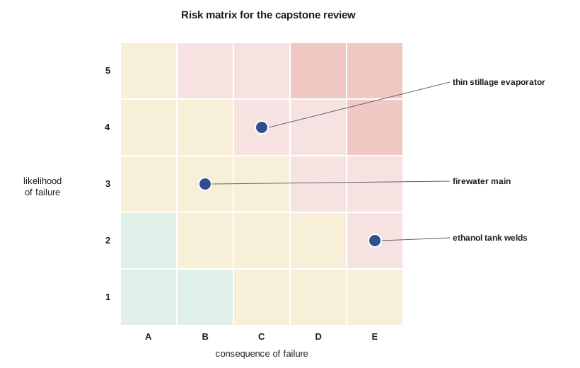
Risk-based inspection (RBI) allocates inspection effort according to risk, the product of the likelihood of failure and its consequence. The American Petroleum Institute's recommended practice for RBI and its companion document on quantitative methods are widely used in refining and chemicals. Likelihood depends on the active damage mechanisms, their rates, the equipment's condition and how effective past inspections were; consequence depends on what would be released, how much, and what it could harm. High-risk items get more frequent and more thorough inspection; low-risk items may be inspected less often than a fixed-interval program would require. RBI also shows where reducing risk by other means, such as a material upgrade or an integrity operating window, is better value than more inspection.
A corrosion management system wraps all of this into a cycle that the plant runs year after year. It identifies corrosion loops and damage mechanisms; sets integrity operating windows for the process variables that drive them; specifies materials, coatings, inhibitors and CP; plans inspection by risk; records and analyzes inspection and monitoring data; assesses damage found against fitness-for-service standards; decides on repair, replacement or continued operation; investigates failures; and reviews the whole program when the process changes. Process changes are where many corrosion surprises begin. A new water source, a different corn supplier, a higher evaporator temperature or a switch in cleaning chemical can change a loop's damage mechanisms overnight. The plant's management of change procedure therefore asks Rafael to review every change that affects process chemistry or temperature.
Theo's capstone: a corrosion review
Theo's report covers the plant's three highest-risk systems, each assessed with the tools from the course. The thin stillage evaporator is the clearest case: its 304L tubes pit under deposits in hot chloride (Lessons 3 and 8), and the extreme-value analysis shows the deepest pits approaching the wall thickness over a full bundle. Theo recommends retubing with duplex 2205 (PREN about 35), a chloride integrity operating window with operator actions, shorter cleaning intervals when chloride is high, and eddy current inspection of a statistically chosen sample of tubes at each shutdown.
The ethanol storage tanks rank second because, although the likelihood of failure is low, the consequence of a large ethanol release is severe. Theo checks the tank records for post-weld heat treatment at critical welds, recommends nitrogen blanketing to keep dissolved oxygen low (Lesson 9), adds wet fluorescent magnetic particle testing of selected welds to the next internal inspection, and recommends checking water bottoms regularly. The third system is the steam and condensate system, where the amine program has cut corrosion rates (Lesson 11) but flow-accelerated corrosion in the wet steam lines and corrosion under insulation on cycling condensate lines remain (Lesson 10). Theo recommends extending the flow-accelerated corrosion grid inspections, prioritizing insulated condensate lines that operate between 50 and 150 °C for CUI inspection, and replacing insulation that serves only for personnel protection with guards.
His final recommendation is about the system rather than any single item: put the plant's corrosion loops, integrity operating windows, inspection data and remaining-life calculations into one database, so that trends are visible and every process change is checked against them. Rafael adds a note to the report before it goes to the plant manager: the cheapest corrosion control is the decision made before the equipment is built, the second cheapest is the window that keeps the process inside its design, and the most expensive is the leak nobody saw coming.
Common mistakes
MistakeAssuming cathodic protection protects the inside of a pipe or equipment in air.
InsteadCP works only where metal and anode share an electrolyte such as soil or water.
MistakeReading CP potentials with the current on and no correction.
InsteadCorrect for the soil voltage drop, usually with instant-off readings.
MistakeTaking thickness readings to look for cracking.
InsteadMatch the inspection method to the damage mechanism; cracks need crack-detection methods.
MistakeIgnoring process changes in the corrosion program.
InsteadReview every change that affects chemistry or temperature through management of change.
Summary and key terms
- Cathodic protection makes the structure a cathode by galvanic anodes or impressed current; it works only in soil or water and is combined with coatings.
- Good coatings reduce CP current from amperes to milliamperes; criteria such as −850 mV polarized against copper-copper sulfate confirm protection.
- Buried pipelines are regulated and need test stations, surveys and records; stray current is a special hazard.
- Inspection methods must match damage mechanisms: thickness for thinning, eddy current for tubes, magnetic particle and penetrant for surface cracks, advanced ultrasonics for weld cracks.
- Remaining life equals the thickness margin divided by the corrosion rate; codes such as API 510 and 570 commonly limit intervals to half the remaining life.
- Risk-based inspection focuses effort on items with the highest likelihood and consequence of failure.
- A corrosion management system cycles through damage mechanisms, operating windows, protection, inspection, assessment and management of change.
- Cathodic protection
- Reducing corrosion by making a metal the cathode of an electrochemical cell, using galvanic anodes or impressed current.
- Sacrificial anode
- A more active metal connected to a structure so that it corrodes and supplies protective current.
- Transformer-rectifier
- A power unit that supplies direct current for an impressed current cathodic protection system.
- Instant-off potential
- A structure potential measured immediately after interrupting the protection current, free of soil voltage drop.
- Condition monitoring location
- A fixed point where thickness or other measurements are repeated over time to find trends.
- Remaining life
- The time until a component reaches its minimum required thickness at the current corrosion rate.
- Risk-based inspection
- Planning inspection by the likelihood and consequence of failure of each item.
Practice problems
Work each problem on paper first, then reveal the answer to check.
Name the two types of cathodic protection and one advantage of each.
Show answer
Galvanic anodes need no power and are simple; impressed current can deliver large currents for big or poorly coated structures.
Why does a good coating reduce the CP current needed?
Show answer
Current is needed only at bare steel, so less exposed area needs less current.
What does the instant-off potential remove from a CP measurement?
Show answer
The voltage drop in the soil caused by the protection current.
Which inspection method suits pitting in heat exchanger tubes?
Show answer
Eddy current testing.
A pipe is 7.2 mm thick, the required thickness is 4.0 mm and the rate is 0.25 mm/y. Find the remaining life and the half-life interval.
Show answer
\((7.2 - 4.0)/0.25 = 12.8\) years; inspect within 6.4 years.
Why should process changes be reviewed by the corrosion engineer?
Show answer
Changes in chemistry or temperature can introduce new damage mechanisms or speed up existing ones.
Lesson quiz · 5 questions
Score 60% or more to complete this lesson.
Create a free account to save your progress, take quizzes and earn a certificate.