
CHE-230 · Lesson 10 of 12 · 23 min
The energy equation with pumps and turbines
Electricity is the largest operating cost at Northside after staff. The three pumps draw roughly 200 kW each when running, and Platte Bluffs Water's energy bill depends on how much head they must develop and how efficiently they develop it. Downstream, the in-line turbine at the pressure-reducing station earns some of that energy back. To analyze both, we need an equation that the Bernoulli equation cannot provide: one that includes shaft work added by a pump or removed by a turbine, and the mechanical energy lost to friction. That is the energy equation for steady flow, written in terms of heads.
From the first law to the energy equation
The first law of thermodynamics, applied to a control volume in steady flow, says that the heat added plus the shaft work added equals the increase in enthalpy, kinetic energy and potential energy of the flow. For liquids in pipe systems, temperature hardly changes, but friction does convert a small amount of mechanical energy into internal energy, warming the water by a tiny amount that is useless for pumping. Gathering that irreversible conversion into a single head-loss term gives the form engineers use.
Each term is a head in meters. The pump head \(h_p\) is the mechanical energy per unit weight added to the water by a pump; the turbine head \(h_t\) is the energy per unit weight removed by a turbine; and the head loss \(h_L\) is the mechanical energy per unit weight dissipated by friction and fittings between sections 1 and 2. Without a pump, turbine or losses, the equation reduces to Bernoulli. The equation applies between two cross-sections, not along a single streamline, so it uses average velocities with kinetic energy correction factors \(\alpha\).
The kinetic energy correction factor
Kinetic energy depends on velocity cubed when integrated over a cross-section with mass flow, so the true kinetic energy flux exceeds the value computed from the average velocity. The factor \(\alpha\) corrects this: it is exactly 2 for fully developed laminar flow and about 1.03 to 1.10 for turbulent flow, depending on the Reynolds number. In water mains the velocity head is often less than a percent of the total head, so taking \(\alpha = 1\) introduces negligible error. Near a nozzle or in a laminar flow of viscous oil, the correction can matter.
Pump head, power and efficiency
The rate at which a pump adds mechanical energy to the water, the water power or hydraulic power, is the weight flow rate times the pump head. The pump itself is not perfect: friction in its bearings and seals, leakage from discharge back to suction and turbulence in the impeller and casing waste some of the shaft power. Pump efficiency \(\eta_p\) is water power divided by shaft power. The motor that drives the pump has its own efficiency, so the electrical input exceeds the shaft power.
Large water pumps reach efficiencies of 85 to 90 percent at their best operating point; small pumps may manage only 50 to 70 percent. Electric motors of this size are 94 to 97 percent efficient. The combined wire-to-water efficiency of a Northside pump set is about 78 percent, which means a fifth of the electricity bought for pumping ends up as heat in the motor, pump and water.
Worked problem
Pumping to the elevated reservoir
A Northside pump delivers 0.30 m³/s (4750 gpm) from the clearwell to the elevated reservoir, whose water surface is 48.0 m (157 ft) above the clearwell's. The head loss in the suction and discharge piping is 6.5 m (21.3 ft) at this flow. The pump is 82 percent efficient and its motor 95 percent. Find the pump head, the shaft power, the electrical input and the annual energy for 16 hours of operation a day.
Show solution
- Sections at the two free surfaces: \(p_1 = p_2 = 0\) gauge, \(V_1 \approx V_2 \approx 0\), \(z_2 - z_1 = 48.0\ \text{m}\).
- Energy equation: \(h_p = (z_2 - z_1) + h_L = 48.0 + 6.5 = 54.5\ \text{m}\) (179 ft).
- Water power \(P_w = 998(9.81)(0.30)(54.5) = 160.1\ \text{kW}\); shaft power \(= 160.1/0.82 = 195.2\ \text{kW}\) (262 hp); electrical \(= 195.2/0.95 = 205.5\ \text{kW}\).
- Annual energy \(= 205.5(16)(365) = 1.20 \times 10^6\ \text{kWh} = 1200\ \text{MWh}\). In customary units, water horsepower is \(Q(\text{gpm}) \times H(\text{ft})/3960 = 4750(179)/3960 = 215\ \text{hp}\).
Answer: One pump uses about 1200 MWh a year. Each meter of head loss saved in the piping would save about 22 MWh a year, a useful figure when deciding whether a larger discharge pipe is worth its cost.
# Energy equation with a pump and a turbine
import math
rho, g = 998.0, 9.81

# Pump lifting water from the clearwell to the elevated reservoir
Q = 0.30                     # m3/s
z1, z2 = 0.0, 48.0           # clearwell surface and reservoir surface, m
hL = 6.5                     # total head loss in suction and discharge piping, m
hp = (z2 - z1) + hL          # both surfaces at atmospheric pressure, negligible velocity
P_water = rho * g * Q * hp
eta_pump, eta_motor = 0.82, 0.95
P_shaft = P_water / eta_pump
P_elec = P_shaft / eta_motor
print(f"Pump head {hp:.1f} m; water power {P_water/1000:.1f} kW")
print(f"Shaft power {P_shaft/1000:.1f} kW; electrical input {P_elec/1000:.1f} kW")
hours = 16 * 365
print(f"Energy per year at 16 h/day: {P_elec/1000*hours/1000:.0f} MWh")

# In-line turbine at the pressure-reducing station
p_in, p_out = 690e3, 280e3   # Pa gauge
Qt = 0.25
D_in, D_out = 0.500, 0.600
V_in, V_out = Qt / (math.pi * D_in**2 / 4), Qt / (math.pi * D_out**2 / 4)
ht = (p_in - p_out) / (rho * g) + (V_in**2 - V_out**2) / (2 * g)
eta_t = 0.78
P_t = eta_t * rho * g * Qt * ht
print(f"Turbine head {ht:.1f} m; electrical output at {eta_t:.0%} overall: {P_t/1000:.0f} kW")

# Kinetic energy correction: laminar alpha = 2, turbulent about 1.05
for alpha in (1.0, 1.05, 2.0):
print(f"alpha = {alpha:4.2f}: velocity head term for V = 2 m/s is {alpha * 2.0**2 / (2*g):.3f} m")Pump head 54.5 m; water power 160.1 kW Shaft power 195.2 kW; electrical input 205.5 kW Energy per year at 16 h/day: 1200 MWh Turbine head 41.9 m; electrical output at 78% overall: 80 kW alpha = 1.00: velocity head term for V = 2 m/s is 0.204 m alpha = 1.05: velocity head term for V = 2 m/s is 0.214 m alpha = 2.00: velocity head term for V = 2 m/s is 0.408 m
Turbines and energy recovery
A turbine reverses a pump's role: water does work on its runner, and the turbine head \(h_t\) is the energy per unit weight extracted. The power delivered to the shaft is \(\eta_t \gamma Q h_t\), where the turbine efficiency is the shaft power divided by the water power given up. Large hydroelectric turbines exceed 90 percent efficiency. Small in-line turbines and pumps run in reverse as turbines, which water utilities use where a pressure-reducing valve would otherwise throw energy away, typically reach 60 to 80 percent overall, including the generator.
At Platte Bluffs Water's pressure-reducing station, water from the high-pressure zone must enter a low-pressure zone at about 280 kPa instead of 690 kPa. A reducing valve would dissipate that difference as turbulence and heat. The in-line turbine extracts the same head as useful work, and the valve now serves only as a bypass when the turbine is out of service. With 0.25 m³/s and a head drop of about 42 m, it generates about 80 kW, enough to power the station that houses it and return some to the grid.
The energy and hydraulic grade lines revisited
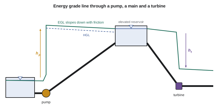
With pumps, turbines and losses included, the energy grade line becomes a powerful design tool. It starts at the surface of the source reservoir, slopes down along each pipe at a rate equal to the friction loss per unit length, drops abruptly at each fitting by its minor loss, jumps up by \(h_p\) at a pump and falls by \(h_t\) at a turbine. The hydraulic grade line follows one velocity head below. At the outlet into a reservoir, the velocity head is lost as the jet mixes into still water, and the EGL meets the reservoir surface.
Two checks follow from the sketch. First, wherever the pipe rises above the HGL, the pressure is below atmospheric, and air can be drawn in at leaky joints or come out of solution; air-release valves are placed at such high points. Second, the pressure at any point equals \(\gamma\) times the distance from the pipe up to the HGL, so the sketch shows directly where pipe pressure ratings could be exceeded, typically at low points just downstream of a pump.
Worked problem
Pressure at a low point on the discharge main
The pump of the earlier example has its discharge flange at elevation 1.0 m above the clearwell surface. The main dips to a low point at elevation −4.0 m, 400 m along, before climbing to the reservoir. The total discharge pipe is 1200 m long with a uniform friction loss, and the suction loss is 0.5 m of the 6.5 m total. Find the pressure at the low point in kPa and psi, neglecting the velocity head.
Show solution
- HGL just after the pump: \(0 - 0.5 + 54.5 = 54.0\ \text{m}\) above the clearwell surface.
- Discharge friction is 6.0 m over 1200 m; at 400 m it has used \(6.0(400/1200) = 2.0\ \text{m}\), so the HGL there is \(52.0\ \text{m}\).
- Pressure head at the low point \(= 52.0 - (-4.0) = 56.0\ \text{m}\); \(p = 9.79(56.0) = 548\ \text{kPa} = 79.5\ \text{psi}\).
Answer: The low point runs at about 550 kPa in steady operation, comfortably within the pipe's rating. A sudden pump trip would add a surge pressure on top, which is why surge analysis checks the same points.
Benchmarking pumping energy
Utilities compare pumping stations with a simple figure, the specific energy: kilowatt-hours used per megaliter pumped. For an ideal pump and motor, lifting one megaliter (10⁶ kg of water) through one meter takes \(\gamma V h = 9.79 \times 10^3 \times 1000 \times 1\ \text{J} = 9.79\ \text{MJ}\), or 2.72 kWh. Dividing by the wire-to-water efficiency gives the real figure. For Northside, with a pump head of 54.5 m and 78 percent wire-to-water efficiency, the specific energy is \(2.72(54.5)/0.78 = 190\ \text{kWh/ML}\).
The figure is useful because it separates the two things an operator can change. Head can be lowered by keeping the reservoir level low when demand allows, by cleaning or enlarging pipes and by opening throttled valves. Efficiency can be raised by running the pumps near their best efficiency point, by trimming impellers to suit the real system or by adding variable-speed drives. Platte Bluffs Water tracks specific energy monthly; a sudden rise usually means a worn impeller, a partly closed valve or a pump running far from its best point.
Where the energy goes
It is worth remembering what head loss is. Mechanical energy is not destroyed; it is converted, through viscous shear in turbulent eddies, into internal energy, raising the water temperature very slightly. A head loss of 10 m corresponds to a temperature rise of only about 0.023 °C, since \(\Delta T = g h_L/c_p\). That conversion is irreversible, and that is why the loss matters: the energy is still there, but it can no longer lift water or turn a turbine. Lessons 11 and 12 show how to calculate \(h_L\) from the pipe's size, length, roughness and fittings.
Common mistakes
MistakeUsing Bernoulli across a pump or turbine.
InsteadUse the energy equation with h_p or h_t and h_L.
MistakeDividing by efficiency for a turbine or multiplying for a pump.
InsteadPump shaft power = water power/η_p; turbine shaft power = η_t × water power.
MistakeAdding head loss on the wrong side of the equation.
Insteadh_L appears on the downstream side, with h_t; h_p appears on the upstream side.
MistakeIncluding the reservoir velocity heads.
InsteadVelocity at large free surfaces is negligible; the exit velocity head into a reservoir becomes a loss.
MistakeTreating head loss as energy destroyed.
InsteadIt is mechanical energy converted irreversibly to internal energy.
Summary and key terms
- The energy equation adds pump head, turbine head and head loss to the Bernoulli terms between two sections.
- Water power is γQh_p; shaft power = water power/η_p; electrical input = shaft power/η_m.
- Turbine output is η_tγQh_t.
- The kinetic energy factor α is about 1.05 in turbulent flow and 2 in laminar flow.
- The EGL slopes down with friction, jumps at pumps and drops at turbines; the HGL is one velocity head below.
- Pressure at any point equals γ times the height of the HGL above the pipe.
- Energy equation
- Mechanical energy balance between two sections including pump head, turbine head and head loss.
- Pump head
- The mechanical energy added by a pump per unit weight of fluid.
- Turbine head
- The mechanical energy removed by a turbine per unit weight of fluid.
- Head loss
- Mechanical energy per unit weight converted irreversibly to internal energy by friction and fittings.
- Water power
- The rate of mechanical energy delivered to the fluid, γQh_p.
- Pump efficiency
- Water power divided by shaft power.
- Wire-to-water efficiency
- Water power divided by electrical input to the motor.
- Kinetic energy correction factor
- A factor α correcting kinetic energy flux for a non-uniform velocity profile.
- Energy recovery turbine
- A turbine installed in place of a pressure-reducing valve to generate power.
Practice problems
Work each problem on paper first, then reveal the answer to check.
A pump lifts 0.12 m³/s through a static lift of 25 m with 4 m of losses. Find the pump head and water power.
Show answer
h_p = 29 m; P_w = 998(9.81)(0.12)(29) = 34.1 kW.
The same pump is 75 % efficient and its motor 93 %. Find the electrical input.
Show answer
34.1/0.75/0.93 = 48.9 kW.
A turbine passes 2.0 m³/s with a net head of 30 m at 88 % efficiency. Find its output.
Show answer
P = 0.88(998)(9.81)(2.0)(30) = 517 kW.
Between two points 800 m apart on a horizontal pipe of constant diameter, the pressure falls from 450 to 380 kPa. Find h_L.
Show answer
h_L = 70/9.79 = 7.15 m.
How much does 25 m of head loss warm the water? (c_p = 4.18 kJ/(kg·K))
Show answer
ΔT = 9.81(25)/4180 = 0.059 K.
In the program, reduce the head loss to 3.5 m. How much electrical power is saved?
Show answer
About 11 kW, from 205.5 to about 194 kW.
Lesson quiz · 5 questions
Score 60% or more to complete this lesson.
Create a free account to save your progress, take quizzes and earn a certificate.