
BAS-440 · Lesson 8 of 12 · 22 min
Review: field devices and wiring
▶ Video coming soon A video version of this lesson is on the way.
The four review lessons were Prakash's idea. "Certification exams, job interviews and service calls all ask the same thing," he said. "Can you put the whole program together when it matters?" For each review he chose a few of the fall's real cases, asked Callie to explain them without notes, and then filled in what she had missed. The first review covered BAS-110, BAS-120 and BAS-210: the building systems, the field devices and the controllers and wiring that connect them.
This lesson works the same way. Each section restates the core ideas, ties them to a case from the program, and ends with the questions Prakash asked. The figures and numbers are the ones used in those courses.
What the controls are for
BAS-110 started from the building, not the controller. A control system exists to keep spaces comfortable, healthy and safe while using as little energy as possible, and every point measures or moves something in the air, water or electrical systems that do that. Callie's first weeks followed the systems from plant to zone: Harcastle's steam plant and Tilden Hall's converter and hot water loop, AHU-1's mixed air and ventilation, Ninefield's chillers and VAV floors, the podium rooftop units and the lighting controls.
- Air systems: air handlers mix outdoor and return air, filter, heat or cool, and deliver air to zones; VAV boxes vary airflow and reheat; fans run on drives to save energy.
- Water systems: boilers and converters make hot water, chillers make chilled water, pumps move it, valves control what each coil receives; delta-T tells how well coils are using it.
- Ventilation: minimum outdoor air sets the healthy baseline; demand-controlled ventilation reduces it when spaces are partly occupied.
- Safety: freezestats, high static limits, smoke detectors and fire alarm interfaces protect equipment and people, and are hardwired where they must work without the controller.
Prakash's first question was about Ninefield's chilled water plant in BAS-110: why a low delta-T of 6.3 °F instead of the design 10 °F mattered. Callie answered that at low delta-T the plant must pump more water for the same cooling, the chillers cannot load fully, and more chillers and pumps run than the load needs; the causes are usually at the coils, such as three-way valves, oversized or leaking valves and low supply air setpoints, which is what the retro-commissioning plan for spring 2027 addresses.
Sensors and their signals
BAS-120 covered how each sensor turns a physical quantity into a signal the controller can read, and how each one goes wrong.
| Signal | How it works | Typical faults | Case from the program |
|---|---|---|---|
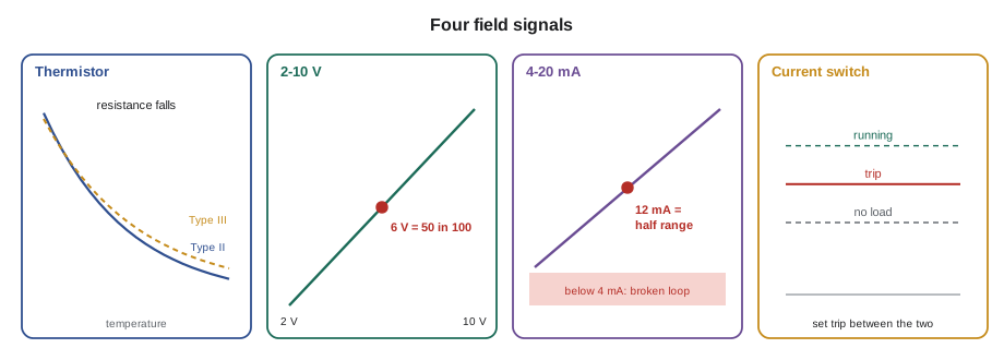
| Thermistor (10K) | Resistance falls as temperature rises; the controller must be set for the right curve | Wrong curve type; drifted element; damaged cable | Tilden's outdoor sensor: a Type III sensor on a Type II input read about 1.3 °F high near 61 °F |
| RTD (Pt1000) | Resistance rises with temperature, nearly linear | Lead resistance on two-wire runs | A long two-wire run adds error that a three- or four-wire connection removes |
| Voltage (0-10 V or 2-10 V) | Voltage proportional to the measured range | Range set differently in sensor and controller; shared commons | Ninefield's penthouse economizer actuators shared a common with analog outputs |
| Current (4-20 mA) | Current proportional to range; 4 mA is live zero, so a broken loop reads below 4 | Loop power budget; wrong scaling | Ninefield's CHW differential pressure transmitter jumped until its shield and routing were fixed |
| Pressure tubes | Pressure measured through tubing to a transducer | Cut, kinked or swapped tubes; poor reference location | Ninefield's building static reference tube cut in a 2024 roofing repair |
| Contact (dry) inputs | Open or closed switch | Wrong normal state; swapped tubes on a pressure switch | A penthouse filter switch with its tubes swapped and wired to the wrong terminal |
| Current switch | Senses motor current for status | Fixed trip too low, so a broken belt still shows on | Tilden EF-3: replaced with an adjustable switch set between no-load and running current |
Worked problem
Reading scaled signals
A damper actuator's feedback is 2-10 V for 0 to 100 in 100 open. A duct pressure transmitter gives 4-20 mA for its full range. What position does 6 V show, and what fraction of range does 12 mA show?
Show solution
- 2-10 V spans 8 V. 6 V is 6 − 2 = 4 V above zero: 4 ÷ 8 = 0.5, so 50 in 100 open.
- 4-20 mA spans 16 mA. 12 mA is 12 − 4 = 8 mA above zero: 8 ÷ 16 = 0.5, so half of range.
Answer: Both are at the middle of their ranges. If the same 6 V were read on an input set for 0-10 V, it would show 60 in 100, which is the kind of mismatch Callie found on Tilden's AHU-1 heating valve in September.
Prakash's question here was what Callie checks first when a temperature reading looks wrong. Her answer followed BAS-120: compare with a reference instrument at the sensor, check the input's configured type and range, measure the raw signal at the controller terminals, and only then suspect the sensor itself. She added a lesson from September: a sensor can be accurate and still give a bad reading if it is in the wrong place, like the seventh-floor humidity sensor in Ninefield's return that was seeing kitchenette air.
Actuators, valves and dampers
Outputs are where control becomes physical, and BAS-120 covered how they are sized and how they fail.
- Actuators are chosen by torque or force, stroke, speed, signal and fail position. Spring-return actuators move to a safe position on power loss; non-spring actuators stay where they are.
- Damper torque depends on area, blade type and seals. Ninefield's RTU-2 outdoor air damper had seals added in 2015 without a larger actuator, and stuck near 20 in 100 open until replaced.
- Valves are sized by flow coefficient (Kv or Cv) and pressure drop. A valve that is too large controls badly, using only part of its stroke; authority, the share of the branch pressure drop taken by the valve, should be high enough for good control.
- Linkages and couplings slip. Room 108's reheat valve stayed open because the actuator had slipped on the valve stem, while the controller showed it closed. A witness mark across a coupling shows slip at a glance.
Callie described how she would check an actuator on a service call: command it to both ends and to the middle, watch the device move, compare feedback with command, check direction and fail position, and look at the coupling. The Wednesday, November 11 checkout of RTU-1 had found an economizer actuator moving in the wrong direction for exactly this reason: nobody had watched the damper while commanding it.
Controllers
BAS-210 covered controllers from the small unitary devices on VAV boxes to programmable plant controllers. Prakash asked Callie to explain the three types and when each is used.
| Type | Typical use | Program | Example |
|---|---|---|---|
| Unitary or application-specific | VAV boxes, fan coils, heat pumps, rooftop units | Fixed application with settings | About 140 box controllers at Ninefield |
| Programmable equipment controller | Air handlers, rooftop units, small plants | Custom program | RTU-1's new BACnet controller (10 universal inputs, 4 universal outputs, 6 relays) |
| Plant or supervisory controller | Central plants, routing, schedules, trends for a building | Custom program; network management | Ninefield's penthouse supervisory controller on three trunks |
Every controller has power, inputs, outputs, communication, memory and firmware, and each of those has its own failure modes. The spare plant controller in the panel shop and the 2011 controller with its scorched triac had shown Callie what a contactor coil without suppression can do to an output. The Morrow House story had shown why Quillon records firmware with every backup: a replacement controller with newer firmware would not accept the old backup, and rebuilding took two days in December 2023.
Power, wiring and grounding
Most field faults are wiring faults, and BAS-210 spent three lessons on power and wiring.
- Class 2 power: a 24 V AC transformer must be sized for the total connected load, with headroom. Loads are added in VA.
- Polarity: on shared transformers, every device must have its common on the same leg; a swapped hot and common can damage devices, as a 2023 entry in the Tilden file recorded.
- Cable: the right type and rating for the space, such as plenum-rated cable where required, kept apart from line-voltage wiring as the electrical code requires.
- Shields: grounded at one end only, usually the controller end, to drain noise without creating a ground loop.
- Separation: signal cables routed away from drive output cables and other noise sources, as the Ninefield CHW differential pressure transmitter showed.
Worked problem
The west stair transformer
Tilden's west stair fan coils shared a 50 VA transformer feeding four controllers at 6 VA each and four spring-return actuators at 10 VA each. What was the connected load, and how loaded was the replacement 100 VA transformer?
Show solution
- Controllers: 4 × 6 = 24 VA.
- Actuators: 4 × 10 = 40 VA.
- Total: 24 + 40 = 64 VA.
- On 100 VA: 64 ÷ 100 = 0.64, or 64 in 100 of rating.
Answer: 64 VA on a 50 VA transformer explains the voltage sag Callie measured, from 25.9 V to 21.3 V at the transformer and 19.8 V at the top controller. The 100 VA replacement leaves headroom, and the label now records both the connected load and the rating.
Prakash's last question was about the safety rule underneath all of it: what work the controls technician does and does not do. Callie answered from BAS-210's roof survey with Declan and Tegan Farrow: Kelso Electric, as the licensed electrical contractor, brought the dedicated 120 V circuit and disconnect to RTU-1 and left it locked off; Quillon's work began at the transformer secondary. Before working in any panel with line voltage present, the technician confirms the source is isolated and locked, tests for absence of voltage, and works only on what is theirs.
Installation quality
The last part of the field review was the one Margit cared about most: workmanship. A panel that is neat, labeled and documented is faster to service for its whole life. BAS-210's RTU-1 panel, built in the shop on Wednesday, October 21, was Prakash's example: terminals numbered to the drawing, every cable labeled at both ends, the transformer sized with headroom (a 40 VA transformer for a 22.5 VA load), a bench test before leaving the shop that found a jumper bar fault, and a label recording who built and checked it. After the Wednesday, November 11 checkout found three faults, the review on Thursday, November 12 added more habits: photograph and relabel the unit's terminal strips, mark sensor cables at the sensor end, record actuator direction, and simulate the unit's terminal strip on the bench before the next three units.
| Check before leaving a panel | Why |
|---|---|
| Every termination tight, no stray strands | Loose terminations cause intermittent faults that take hours to find |
| Labels at both ends of every cable | Lets the next person trace a point without opening ceilings |
| Transformer load and rating on the label | Prevents the next added device from overloading it |
| Shield grounded at one end only | Avoids noise and ground loops |
| Drawing updated with any change (red line) | Keeps the record true |
| Controller backed up, firmware recorded | Makes replacement quick |
The tools of the trade
The field review ended with Callie's tool bag, because the right tool makes most field checks quick and the wrong one makes them misleading. Prakash went through it item by item.
| Tool | Used for | Habit |
|---|---|---|
| Digital multimeter | Voltage, resistance, continuity, current with a clamp | Check it on a known source before trusting a reading of zero |
| Loop calibrator | Sourcing or measuring 4-20 mA and 0-10 V signals | Simulate a transmitter to test an input without the device |
| Reference thermometer | Checking temperature sensors in place | Keep its calibration certificate current |
| Digital manometer | Duct, building and filter pressures; airflow pickups | Zero it before each reading; check tubes for kinks |
| Laptop with tools and cables | Programming, backups, network checks | Up to date, encrypted, and connected only where permitted |
| Hand tools and labels | Terminations, mounting, labeling | Label at both ends before leaving |
The laptop deserved its own warning, which came from BAS-430: it is the tool most able to cause harm. It connects only to the networks and ports the site allows, never bridges two networks, and is kept updated and encrypted. Prakash's rule was that a laptop left in a van overnight should never hold anything that would worry the owner if it were stolen.
Common mistakes
MistakeReplacing a sensor before checking the input configuration.
InsteadCheck the configured type and range, then the raw signal, then the sensor.
MistakeTrusting feedback without watching the device move.
InsteadWatch the valve or damper while commanding it, and check couplings for slip.
MistakeAdding devices to a transformer without adding up the load.
InsteadSum the VA of every connected device and keep headroom.
MistakeGrounding shields at both ends.
InsteadGround at one end only, normally at the controller.
MistakeDoing line-voltage work because it is quick.
InsteadLeave line-voltage work to the licensed electrician; isolate, lock and test before working in any panel.
Summary and key terms
- Controls exist to keep spaces comfortable, healthy and safe with the least energy; every point serves an air, water or electrical system.
- Sensors produce resistance, voltage, current, pressure or contact signals, each with known faults.
- Scaled signals must match between device and controller: 2-10 V and 4-20 mA have live zeros.
- Actuators are sized for torque and fail position; valves for flow coefficient and authority; couplings can slip.
- Controllers range from unitary to programmable plant controllers; firmware and backups must match.
- Class 2 transformers are sized by total VA; polarity, cable type, shields and separation prevent most wiring faults.
- Good workmanship and documentation make every later service call shorter.
- Live zero
- A signal range whose zero is above zero volts or milliamps, so a broken circuit can be detected.
- Valve authority
- The share of a branch's pressure drop taken by the control valve.
- Witness mark
- A line across a coupling or shaft that shows if it has slipped.
- Connected load
- The total VA of all devices supplied by a transformer.
- Spring return
- An actuator that moves to a set position when power is lost.
Practice problems
Work each problem on paper first, then reveal the answer to check.
What does 12 mA mean on a 4-20 mA transmitter?
Show answer
Half of its range.
Five controllers at 6 VA and five actuators at 10 VA share a transformer. What is the load?
Show answer
30 + 50 = 80 VA, so a transformer rated above 80 VA, with headroom, is needed.
Why did Tilden's outdoor sensor read high?
Show answer
A Type III thermistor was connected to an input configured for Type II.
Where is a shield normally grounded?
Show answer
At one end only, usually the controller end.
Lesson quiz · 5 questions
Score 60% or more to complete this lesson.
Create a free account to save your progress, take quizzes and earn a certificate.