
SMW-420 · Lesson 4 of 12 · 19 min
Producing and approving shop drawings
With the Eastgate level 2 area coordinated and signed off, Lin Zhao's team turned the fabrication model into a package of shop drawings for submission. This lesson walks through what goes into a complete ductwork shop drawing package, how the sheets are laid out, how hanger layouts and fitting tags are presented, how the package is checked and submitted, and how revisions are controlled once the drawings are approved and the shop is cutting metal. Kai Ferreira prepared his first real sheet in this package, the hanger layout for the level 2 east corridor, under Lin's supervision.
What goes in a package
A ductwork submittal package for one area normally contains a cover sheet listing the drawings and the specification sections they respond to; a legend and general notes sheet; floor plans at a working scale with all ductwork, sizes, elevations, fitting tags and accessories; enlarged plans of mechanical rooms and congested areas; sections at key crossings; riser diagrams for shafts; detail sheets for supports, fire damper installations, roof curbs, access doors and connections to equipment; and a fitting schedule or fabrication list. The specification usually lists the minimum content, and the engineer's comments on earlier packages often add to it.
The general notes are worth more attention than they get. They state the construction standard and edition the ductwork follows, the pressure and seal classes for each system, the gauge and reinforcement basis, the joint types used, the sealant and tape products, the insulation basis, the support standard and any project-specific requirements such as the hospital's infection-control cleaning and capping of open duct ends. If the engineer accepts the notes, every sheet in the package carries those decisions; if the notes are vague, the engineer will ask questions on every sheet.
| Sheet | Contents |
|---|---|
| Cover | Drawing list, specification sections, submission and revision record |
| Legend and notes | Symbols, abbreviations, standards, pressure and seal classes, joints, sealants |
| Floor plans | Double-line duct, sizes, BOD elevations, tags, dampers, access doors |
| Enlarged plans and sections | Mechanical rooms, shafts and congested crossings |
| Hanger layout | Hanger and insert locations, types and loads |
| Details | Supports, fire dampers, curbs, flexible connections, terminal connections |
| Fitting schedule | Every tagged fitting with its code, dimensions, gauge and connectors |
Plans and sections
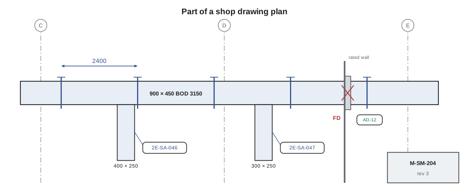
The floor plans are the heart of the package. Lin's rule is that a plan must be readable at arm's length on a site table: dimension strings outside the duct, tags in boxes along the run with leaders, elevations in a consistent place, and no text crossing another line. Background architectural and structural information is shown screened back. Systems are distinguished by line type and by the system abbreviation in each size label, such as SA for supply, RA for return, EA for general exhaust and IEA for isolation exhaust on Eastgate, because a black-and-white print cannot rely on colour.
Sections are cut wherever the vertical arrangement matters. The level 2 east corridor section shows, from the slab down, the structural beams with fireproofing, the cable trays along one side, the sprinkler main, the supply main below the beams, the return air path, the medical gas pipes and the ceiling grid, each with its elevation. The section is often the drawing the other trades and the engineer study most closely, because it shows that the coordination agreed in the model is really buildable.
Hanger layouts
Hangers deserve their own sheet on a hospital job. The hanger layout shows every support location dimensioned to gridlines, the hanger type from the detail sheet (for example strap, rod and trapeze, or seismic brace), the attachment to structure (cast-in insert, post-installed anchor, beam clamp), and the load. Keelson's supports follow the spacing and sizing tables in the support standard the specification calls for, as covered in SMW-310, and seismic bracing follows the engineer's or the seismic designer's requirements. Because Eastgate's slabs were poured with cast-in inserts, the hanger layout had to be finished and coordinated before the concrete was placed, well before the duct shop drawings for those floors were approved.
# Hanger layout along a straight run: count and load per hanger
run_length = 27.6          # length of the run, m
spacing = 2.4             # maximum hanger spacing for this duct size, m
duct_mass = 38           # duct, insulation and accessories, kg per m
import math
spans = math.ceil(run_length / spacing)
hangers = spans + 1
actual = run_length / spans
load = duct_mass * actual
print(f"{hangers} trapeze hangers at {actual:.2f} m spacing")
print(f"load per trapeze about {load:.0f} kg (split between two rods)")13 trapeze hangers at 2.30 m spacing load per trapeze about 87 kg (split between two rods)
Kai's first sheet showed the east corridor main on 13 trapeze hangers at even spacing, each with two rods into cast-in inserts. Lin checked the layout against the beams in the model and moved two hangers that landed in the fireproofing at a beam flange, where an insert could not be cast. She also added an extra hanger at each fire damper, because the damper sleeve and its retaining angles add weight and the damper must be supported independently of the wall where the installation instructions require it.
Fitting tags and spool sheets
Every piece on the drawings carries a tag that is unique on the project. Keelson's tags combine the level, the area or system and a running number, such as 2E-SA-047 for supply fitting 47 in the level 2 east area. The tag appears on the plan, in the fitting schedule, on the printed label stuck to the metal in the shop and in the tracking system covered in Lesson 11. On large runs, Lin groups fittings into spools: an assembly of a few joints and fittings that the shop pre-assembles and ships as one piece, with its own spool sheet showing the parts, the order of assembly and the joint locations.
Spooling saves field labour, because joining and sealing on a bench in the shop is faster and better than on a ladder, but spools are limited by what can be lifted, moved through the building and fitted through openings. On Eastgate's occupied-floor connection, the largest spool had to fit through an existing corridor door and into the service elevator, which set its length. Lin checks every spool against the delivery and installation route as well as against the trucks.
Checking and submitting
Before submission the package goes through Keelson's internal check, which includes the drawing checklist from Lesson 2 plus package-level checks: that the drawing list matches the sheets, that every specification requirement is addressed or an exception is clearly noted, that product data for dampers, sealants and access doors is attached or referenced, and that the package matches the coordinated model sign-off date. Lin then sends the package to Northpoint Mechanical with a transmittal that lists the sheets and revisions and asks for the review needed. The transmittal also notes any items Keelson needs answered quickly, such as an open RFI that affects a shaft.
Any deviation from the specification must be called out, not hidden. If Keelson proposes a different joint, an alternative sealant or a change in duct shape under a beam, the transmittal and the drawing note it clearly and give the reason. A deviation that is buried in a drawing and passes review unnoticed is not approved, because the contract usually says that review does not authorise deviations unless they are specifically identified. Honest, visible notes protect Keelson as much as they help the engineer.
Responding to comments
The level 2 package came back reviewed as noted, with eleven comments. Most were small: two missing access doors at fire dampers, a wrong system abbreviation, a request to show a cleanout on the isolation exhaust and a reminder that the isolation exhaust duct must be sealed to the highest seal class. One comment asked Keelson to relocate a volume damper to make it reachable from a ceiling access panel. Lin logged each comment in a comment register with the sheet, the change made and the new revision number, and returned the register with the revised sheets so that the engineer could see that every comment had been addressed.
# A comment register summary
comments = [("access door at fire damper", "S-302", "added", 1), ("access door at fire damper", "S-303", "added", 1),
            ("system label", "S-302", "corrected", 1), ("isolation exhaust cleanout", "S-305", "added", 1),
            ("seal class note", "S-300", "added", 1), ("volume damper location", "S-304", "moved", 1)]
for c, sheet, action, rev in comments:
    print(f"{sheet}  rev {rev}  {c:30s} {action}")
open_items = [c for c in comments if c[2] not in ("added", "corrected", "moved")]
print(f"open comments: {len(open_items)}")S-302 rev 1 access door at fire damper added S-303 rev 1 access door at fire damper added S-302 rev 1 system label corrected S-305 rev 1 isolation exhaust cleanout added S-300 rev 1 seal class note added S-304 rev 1 volume damper location moved open comments: 0
Revision control after approval
Approval is not the end of revision control; it is the start of the most important part. Once the shop is cutting from approved drawings, any change has to be managed so that the shop, the field and the record all stay in step. Keelson's process is simple: the change is made in the model; the affected sheets are revised with clouds and a new revision number; the fabrication list is regenerated and compared with the previous one so that only the changed pieces are released or held; the shop foreman, Walt Szymanski, is told which tags are affected; and the field receives the new sheets with the old ones marked void. A change that has already been fabricated is flagged so that the cost can be claimed if the change was not Keelson's doing.
At the end of the job, the drawings become the as-built record. Field crews mark up any deviations from the shop drawings, such as a run that moved to avoid an unexpected obstruction, and the drawing office updates the model and sheets. On a hospital, accurate as-builts of ductwork, dampers and access doors are valuable to the owner for decades, because every future renovation, damper inspection and infection-control project starts from them.
Worked problem
Placing hangers around a fire damper
A straight 27.6 m run is to be hung at a maximum spacing of 2.4 m, and a fire damper sits at 12.0 m from the start. The damper's installation instructions require the duct to be supported within 600 mm on each side of the damper. How many hangers are needed?
Show solution
- Even spacing first: 27.6 / 2.4 = 11.5, so 12 spans and 13 hangers.
- The even layout puts hangers at 11.5 m and 13.8 m, which do not both fall within 600 mm of the damper.
- Add a hanger on each side of the damper at the allowed distance, and keep the rest of the layout within the maximum spacing.
- Result: 13 hangers in the regular layout, adjusted, plus the damper supports, for 14 or 15 hangers in total depending on how the spacing is redistributed.
Answer: Hanger layouts follow maximum spacing first and then the accessories' own support requirements.
Checking a package before it goes out
Before Lin signs a package for submittal, a second detailer checks it against a written checklist: every run has a size and an elevation, every fitting has a tag that appears on the fitting list, every damper has an access door, every penetration of a rated assembly has the right damper type, hanger spacing meets the standard, and the title block and revision table are complete. Most packages come back from this internal check with a few corrections, and catching them in-house is far cheaper than a revise and resubmit stamp from the engineer.
Common mistakes
MistakeLeaving general notes vague.
InsteadState the standards, pressure and seal classes, joints, sealants and supports clearly so every sheet carries those decisions.
MistakeBurying a deviation from the specification in a drawing.
InsteadIdentify every deviation clearly on the drawing and in the transmittal.
MistakeFinishing hanger layouts after the slabs are poured.
InsteadFinish and coordinate the insert layout before concrete placement.
MistakeMaking a change on one sheet but not regenerating the fabrication list.
InsteadChange the model, revise all affected sheets and compare fabrication lists.
MistakeMaking spools too large for the delivery route.
InsteadCheck each spool against doors, elevators and lifting limits as well as trucks.
Summary and key terms
- A package includes a cover, legend and notes, plans, sections, hanger layouts, details and a fitting schedule.
- General notes carry key decisions on standards, classes, joints, sealants and supports.
- Hanger layouts are dimensioned to gridlines and coordinated with inserts and accessories early.
- Unique tags link plans, schedules, labels and tracking; spools are checked against the delivery route.
- Deviations must be identified clearly; comments are answered in a register.
- After approval, changes go through the model, revised sheets and a fabrication list comparison, and drawings end as as-builts.
- General notes
- Notes on a drawing set stating the standards, classes, materials and methods that apply.
- Hanger layout
- A drawing showing the location, type and load of every duct support.
- Spool
- A shop-assembled group of joints and fittings shipped and installed as one piece.
- Transmittal
- A cover document listing what is being sent, why and what response is needed.
- Comment register
- A log of review comments and how each was addressed.
- As-built
- A drawing updated to show the work as it was actually installed.
Practice problems
Work each problem on paper first, then reveal the answer to check.
What is the purpose of the general notes sheet?
Show answer
To state the standards, pressure and seal classes, joints, sealants, insulation and supports that apply to all sheets.
Why did the Eastgate hanger layout have to be finished early?
Show answer
The slabs were poured with cast-in inserts, so the insert locations had to be known before concrete placement.
A deviation from the specification passed review without being noted. Is it approved?
Show answer
Usually not: review does not authorise deviations unless they are specifically identified.
What limits the size of a spool on a renovation connection?
Show answer
Doors, corridors, elevators and lifting limits on the delivery and installation route.
Lesson quiz · 5 questions
Score 60% or more to complete this lesson.
Create a free account to save your progress, take quizzes and earn a certificate.