
ROB-320 · Lesson 8 of 12 · 29 min
Memory and resource management
Real-time systems fail in time and in space. A control loop can miss its deadline, but it can also overflow its stack, run out of heap after three days of uptime, or have its variables overwritten by a buggy logging task. Memory faults are among the hardest embedded bugs to find, because the code that crashes is often not the code that caused the damage. This lesson covers how memory is laid out on a microcontroller, why dynamic allocation is avoided or tightly controlled in real-time code, how to size and monitor stacks, how memory protection units contain faults, and the coding rules, such as MISRA C, that safety-related robot software commonly follows.
The memory map of an embedded program
A microcontroller program occupies a few distinct regions. Code and constant data live in flash. RAM holds the data section (initialized globals, copied from flash at start-up), the bss section (zero-initialized globals), the heap (memory handed out at run time by malloc or an RTOS allocator) and one or more stacks: the main stack used at start-up and by interrupt handlers, and in an RTOS a separate stack for each task. Many processors also have small tightly coupled memories, fast RAM directly attached to the core with single-cycle access and no cache effects, which are ideal for the hottest control code and its data.
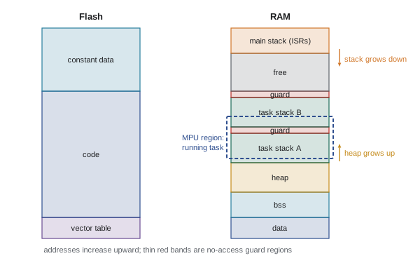
The linker script decides where everything goes, and the map file it produces lists the size and address of every function and variable. Reading the map file is a basic real-time skill: it shows which modules use the most RAM, whether critical code landed in fast memory, and how much space is left.
Why dynamic allocation is avoided
General-purpose malloc and free have two problems for real-time code. Their execution time is variable and often unbounded, because the allocator searches free lists that change with the history of allocations. And repeated allocation and freeing of different-sized blocks fragments the heap: after hours or days, enough memory may be free in total but not in any single block large enough for a request, so an allocation fails in a system that passed every test. Both problems get worse the longer the system runs, which is exactly the wrong property for a robot expected to run for weeks.
The common rules are therefore: allocate everything at start-up and never free it; use fixed-size block pools, whose allocate and free operations take constant time and cannot fragment; or use static allocation throughout. FreeRTOS supports fully static creation of tasks, queues and semaphores (the xTaskCreateStatic family), and offers several heap implementations, from heap_1, which allocates but never frees, to heap_4 and heap_5, which coalesce free blocks. Zephyr provides memory slabs (fixed-size blocks) and statically defined kernel objects. In C++ robot code on Linux, real-time threads avoid heap allocation in the control loop by preallocating containers, reserving vector capacity and using custom allocators; ROS 2's real-time guidance makes the same point.
# Fragmentation: interleaved lifetimes leave free memory in small pieces
HEAP = 64 * 1024
blocks = []                        # (start, size, kind)
addr = 0
while addr + 264 <= HEAP:          # a message buffer, then a long-lived record
    blocks.append((addr, 200, "msg")); addr += 200
    blocks.append((addr, 64, "rec")); addr += 64
used = sum(n for a, n, k in blocks)
# later, all short-lived message buffers are freed; records stay
free = [(a, n) for a, n, k in blocks if k == "msg"] + [(addr, HEAP - addr)]
total_free = sum(n for a, n in free)
largest = max(n for a, n in free)
print("heap %d bytes, %d blocks allocated" % (HEAP, len(blocks)))
print("after freeing messages: %d bytes free (%.0f %%)" % (total_free, 100 * total_free / HEAP))
print("largest free block: %d bytes in %d pieces" % (largest, len(free)))
for request in (128, 512, 1500):
print("request %4d bytes:" % request, "ok" if largest >= request else "FAILS")heap 65536 bytes, 496 blocks allocated after freeing messages: 49664 bytes free (76 %) largest free block: 200 bytes in 249 pieces request 128 bytes: ok request 512 bytes: FAILS request 1500 bytes: FAILS
Three quarters of the heap is free, yet no request larger than 200 bytes can succeed, because every free piece is trapped between long-lived records. Real heaps fragment more slowly and less neatly, through the random interleaving of allocations with different lifetimes, but the end state is the same. A fixed-size pool for each common block size cannot fragment this way, because any freed block fits any future request of the same size.
Stacks: sizing and overflow
Each task's stack holds its local variables, function return addresses and saved registers, and in a preemptive kernel its full context when it is not running. Interrupt handlers on Cortex-M use a separate main stack, which must hold the deepest possible nesting of interrupts. A stack that is too small overflows silently into whatever lies next to it, corrupting another task's data or a kernel structure; a stack that is too large wastes scarce RAM. Stack overflow is one of the most common causes of mysterious resets in embedded robots.
There are two ways to size stacks. Static analysis tools compute the worst-case depth from the call graph and each function's frame size, which compilers such as GCC report with the -fstack-usage option; this is exact for code without recursion or function pointers, which is one reason coding standards ban recursion. Measurement uses stack painting: fill each stack with a known pattern at start-up, run the system hard, and see how much of the pattern has been overwritten. FreeRTOS reports this as the high-water mark (uxTaskGetStackHighWaterMark), the minimum free stack ever seen.
Worked problem
Worst-case stack depth from a call graph
A control task's entry function uses 48 bytes and calls either compute_control (112 bytes, which calls matrix_mul at 256 bytes) or log_event (80 bytes, which calls format_number at 160 bytes and then uart_write at 64 bytes). Saved context on preemption takes 64 bytes, plus 136 more if the floating-point unit is in use. What is the worst-case stack depth?
Show solution
- Path through compute_control: \( 48 + 112 + 256 = 416 \) bytes.
- Path through log_event: deepest branch \( 48 + 80 + 160 = 288 \) bytes.
- Worst path: 416 bytes, plus context \( 64 + 136 = 200 \) bytes, gives 616 bytes.
Answer: The worst case is 616 bytes. With a 50 % margin for code changes, allocate 1 kB. Note that matrix_mul's large frame, probably a local array, dominates; making that array static would cut the stack by about 200 bytes.
Overflow detection should be on in every build that goes near a robot. RTOSes can check the stack pointer and a guard pattern at each context switch (FreeRTOS's configCHECK_FOR_STACK_OVERFLOW), Armv8-M processors have stack-limit registers that fault immediately on overflow, and a memory protection unit can place a no-access guard region at the end of each stack so that the first stray access faults instead of corrupting data.
| Technique | Catches overflow | Cost | Notes |
|---|---|---|---|
| Static stack analysis (-fstack-usage plus call graph) | Before run time | Build-time effort | Exact without recursion or function pointers |
| Stack painting and high-water mark | Measures peak use | Small RAM and start-up time | Only sees paths exercised in testing |
| RTOS guard check at context switch | After the fact, at the next switch | A few cycles per switch | Damage may already have occurred |
| Hardware stack limit register (Armv8-M) | Immediately | None at run time | Needs a supporting core |
| MPU guard region | Immediately | One MPU region per stack | Also catches stray pointer writes |
Memory protection
A memory protection unit (MPU), found on most Cortex-M3 and higher cores and on Cortex-R processors, lets privileged code define a small number of regions (typically 8 or 16) with access permissions: read-only, read-write, no execute, privileged only. A task that touches memory outside its regions triggers a fault instead of silently corrupting something. MPUs differ from the memory management units of application processors: they do not translate addresses or provide virtual memory, so they add almost no timing uncertainty, which suits real-time use. Zephyr's user mode and FreeRTOS's MPU ports run tasks unprivileged with access only to their own stacks and explicitly shared regions, so a bug in a communications task cannot overwrite the control task's data.
Protection is how mixed-criticality systems are built. A robot controller may combine a safety-related joint monitor, a hard real-time control task and a large, frequently updated communications stack. Placing them in separate protection domains, or on separate cores, contains faults so that a bug in the large, less trusted code cannot break the small, trusted code. Lesson 11 returns to this as freedom from interference, a requirement of the functional safety standards.
Worked problem
MPU region budget
An MPU has 8 regions. Two are fixed for flash code and peripherals. Each running task needs its own stack region and a guard region, and the control task also needs a region for a shared joint-state buffer. How many regions are left for other shared buffers while the control task runs?
Show solution
- Fixed: 2 regions.
- Control task stack and guard: 2 regions.
- Shared joint-state buffer: 1 region.
- Used: 5 of 8.
Answer: Three regions remain for other shared buffers or devices. Because regions are reprogrammed at each context switch, each task gets its own set; the limit applies per task, which is why shared data is often grouped into a few aligned blocks.
Coding standards for real-time and safety code
Many robot companies, and all safety-certified projects, write embedded C to a coding standard. MISRA C, first published by the Motor Industry Software Reliability Association in 1998 and now in its 2023 edition, is the most widely used. Its rules restrict the parts of C whose behaviour is undefined, implementation-defined or error-prone: no dynamic memory allocation after initialization, no recursion, explicit types and casts, no unreachable code, limited use of pointers, and every switch with a default case. Many rules exist precisely to make timing and memory possible to analyse: banning recursion makes worst-case stack depth computable, and banning heap use after start-up removes fragmentation and unbounded allocation time. AUTOSAR's C++14 guidelines and the MISRA C++ 2023 standard play the same role for C++, and CERT C focuses on security. Static analysis tools check conformance automatically, and deviations must be justified and recorded.
Rust is attracting interest in embedded robotics because its ownership rules prevent data races and many memory errors at compile time, and it can run without a heap. A safety-qualified Rust compiler (Ferrocene) has been certified to ISO 26262 and IEC 61508, which has started to make Rust usable in safety-related projects, though C and C++ remain dominant in shipped robot firmware.
Other resources: buses, peripherals and energy
Memory is not the only shared resource with timing consequences. A single SPI or I2C bus shared by several sensors serializes their transfers, so a long transfer to one device delays the others; the bus is a resource with its own critical sections, and its worst-case wait belongs in the blocking term of each task that uses it. DMA channels, hardware timers and crypto accelerators are similar. On battery-powered robots, energy is also a resource: low-power modes save energy but add wake-up latency, which must be counted in interrupt latency budgets.
Worked problem
Bus contention as blocking
An IMU task (high priority, 1 kHz) and a barometer task (low priority, 50 Hz) share an SPI bus protected by a mutex. The barometer's transfer holds the bus for 180 µs; the IMU's takes 40 µs. What blocking can the IMU task suffer, and how could it be reduced?
Show solution
- If the barometer holds the bus when the IMU task is released, the IMU waits up to 180 µs.
- With priority inheritance this is bounded, but still adds 180 µs to the IMU task's response time.
Answer: Blocking of up to 180 µs. Options: split the barometer read into shorter transfers, move the barometer to a separate bus, or let a single high-priority driver task own the bus and serve both sensors in a fixed schedule.
Common mistakes
MistakeCalling malloc and free in the control loop
InsteadAllocate at start-up, use fixed-size pools or static allocation.
MistakeGuessing stack sizes and never checking them
InsteadUse static analysis and high-water marks, and keep overflow detection on.
MistakePutting large arrays in local variables
InsteadMake large buffers static or allocate them once at start-up.
MistakeLetting every task access all memory
InsteadUse the MPU to give each task only the regions it needs.
MistakeTreating a shared bus as free
InsteadCount bus waits as blocking in the timing analysis.
Summary and key terms
- Embedded programs place code in flash and data, bss, heap and stacks in RAM, with fast tightly coupled memory for critical code.
- General-purpose allocation has variable timing and fragments the heap over long run times.
- Real-time code allocates at start-up, uses fixed-size pools or allocates statically.
- Stacks are sized by call-graph analysis and checked by painting and high-water marks.
- Overflow is caught by RTOS checks, hardware stack limits and MPU guard regions.
- A memory protection unit contains faults between tasks with little timing cost.
- Coding standards such as MISRA C restrict features that make timing and memory impossible to analyse.
- Linker script
- The file that tells the linker where code and data go in memory.
- Heap
- Memory handed out at run time by an allocator.
- Fragmentation
- Free memory split into pieces too small for future requests.
- Memory pool
- A set of fixed-size blocks allocated and freed in constant time.
- Stack painting
- Filling a stack with a pattern to measure how much is used.
- High-water mark
- The minimum free stack space ever observed.
- Stack overflow
- A stack growing past its allocated space into other memory.
- MPU
- Memory protection unit: hardware that enforces access permissions on memory regions.
- Tightly coupled memory
- Fast RAM attached directly to the core with predictable access time.
- MISRA C
- A widely used set of rules for safer embedded C that is easier to analyse.
Practice problems
Work each problem on paper first, then reveal the answer to check.
Name two problems with malloc in real-time code.
Show answer
Variable execution time and fragmentation.
Which FreeRTOS heap never frees memory?
Show answer
heap_1.
What GCC option reports per-function stack use?
Show answer
-fstack-usage.
A call path uses 300 bytes and context saving 200 bytes. What is the worst case?
Show answer
500 bytes.
What does the high-water mark report?
Show answer
The minimum free stack space seen.
How does an MPU differ from an MMU?
Show answer
No address translation or virtual memory; just region permissions.
Why does MISRA C ban recursion?
Show answer
So worst-case stack depth can be computed.
What makes fixed-size pools immune to fragmentation?
Show answer
Any freed block fits any later request of the same size.
Where should a DMA buffer go on a cached core?
Show answer
Non-cacheable memory, or use cache maintenance.
How should a shared SPI bus appear in timing analysis?
Show answer
As a blocking term for each task that uses it.
Lesson quiz · 5 questions
Score 60% or more to complete this lesson.
Create a free account to save your progress, take quizzes and earn a certificate.