
ROB-220 · Lesson 2 of 12 · 29 min
Position and motion sensing: encoders, potentiometers and resolvers
Every robot joint needs to know where it is, and nearly every wheel needs to know how far it has turned. The sensors that answer these questions are the workhorses of robotics: rotary and linear encoders, potentiometers, resolvers and the newer magnetic angle sensors. They are proprioceptive, they feed the innermost control loops, and their errors propagate straight into everything the robot computes about its own body. This lesson explains how each type works, how to turn its raw output into angle, speed and distance, and how to choose among them. ROB-200 showed how a microcontroller decodes quadrature signals in hardware; here we concentrate on the sensors and on what their numbers mean.
Potentiometers: the simplest angle sensor
A potentiometer is a resistive track with a sliding contact, the wiper. Apply a reference voltage across the track and the wiper voltage is proportional to its position, so the output gives absolute angle directly. Hobby servos use a potentiometer on the output shaft, and many low-cost linear actuators contain a linear potentiometer for position feedback. The attractions are low cost, absolute output and simple electronics.
The drawbacks are just as clear. The wiper wears, so the track becomes noisy after millions of cycles; most rotary potentiometers cover less than one turn, often around 270° to 340°, with a dead zone; and accuracy is limited by track linearity, typically ±1 % to ±3 % of full scale for inexpensive parts. Because the output is a ratio of two voltages, using the same reference for the potentiometer and the converter cancels supply variations, a ratiometric connection worth making whenever possible.
Worked problem
Reading a servo potentiometer
A potentiometer with 300° of electrical travel is powered from the same 3.3 V reference as a 12-bit converter. The converter reads 2,730 counts. What is the angle, and what is the angular resolution?
Show solution
- Fraction of travel: \( 2730/4095 = 0.667 \).
- Angle: \( 0.667 \times 300° = 200° \).
- Resolution: \( 300°/4095 \approx 0.073° \) per count, though noise and track linearity will limit the useful resolution to well above this.
Answer: About 200° from the start of travel, with a nominal resolution of 0.073° per count.
Incremental optical encoders
An incremental encoder produces pulses as it turns. In the optical version, a disc with a ring of transparent and opaque slots rotates between a light source and photodetectors. Two detectors are placed so that their signals, channels A and B, are a quarter of a cycle apart: in quadrature. The order in which the edges arrive gives the direction of rotation, and counting every rising and falling edge of both channels (4× decoding) gives four counts per slot. A third channel, the index or Z pulse, fires once per revolution and provides a reference for homing.
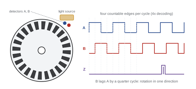
Encoder resolution is quoted in lines (or pulses) per revolution, PPR, which is the number of slots. With 4× decoding the counts per revolution, CPR, is four times larger. Manufacturers do not always make the distinction clear, so check whether a figure of 4,000 means 1,000 lines decoded 4× or 4,000 lines.
Because an incremental encoder only counts changes, its reading is meaningless after power-up until the axis has been homed, usually by driving to a limit switch or index pulse. If the counter misses edges, because of electrical noise or because the shaft spins faster than the decoder can follow, the error persists until the next homing. Losing counts silently is one of the classic failures in motion control, which is why safety-related axes often use a second, independent position sensor.
Worked problem
Wheel distance and speed from an encoder
A robot wheel of diameter 150 mm is driven through a 30:1 gearbox. The motor carries a 500-line incremental encoder decoded 4×. In a 10 ms control period the counter advances by 1,200 counts. How far does the wheel travel per count, and how fast is the robot moving?
Show solution
- Counts per motor revolution: \( 4 \times 500 = 2000 \). Counts per wheel revolution: \( 2000 \times 30 = 60\,000 \).
- Wheel circumference: \( \pi \times 0.150 = 0.4712 \) m. Distance per count: \( 0.4712/60\,000 = 7.85 \times 10^{-6} \) m.
- Distance in 10 ms: \( 1200 \times 7.85 \times 10^{-6} = 9.42 \times 10^{-3} \) m. Speed: \( 0.00942/0.010 = 0.942 \) m/s.
Answer: About 7.9 µm per count and a speed of 0.94 m/s. The fine resolution is real only while the tyre does not slip and its effective diameter stays at 150 mm, which is why wheel odometry drifts (lesson 7).
Measuring speed from counts
Speed can be estimated from encoder counts in two ways. The frequency method counts edges in a fixed time window, as in the example above; it works well at high speed but becomes coarse at low speed, where only a few counts arrive per window. At 1 count per 10 ms window, the speed estimate jumps between 0 and the equivalent of 100 counts per second, a very noisy signal. The period method instead measures the time between consecutive edges with a fast timer; it is precise at low speed but slow to update and noisy at high speed, where the intervals become very short. Good motion controllers switch between the methods or combine them, and many hardware decoders capture both a count and a timestamp for each edge so that software can do so.
| Speed estimate | Best at | Weakness | Resolution limited by |
|---|---|---|---|
| Count edges in a fixed window | High speed | Quantized at low speed | Window length |
| Time between edges | Low speed | Slow updates, short intervals at high speed | Timer clock frequency |
| Combined or observer-based | All speeds | More software | Model quality |
Absolute encoders
An absolute encoder reports a unique code for every position, so it knows the angle immediately at power-up. Optical absolute encoders use several concentric tracks, one per bit, usually in Gray code, in which only one bit changes between neighbouring positions. With ordinary binary, a transition from 0111 to 1000 changes four bits at once, and if the detectors switch at slightly different moments the encoder can briefly report any value; Gray code removes that hazard. Modern absolute encoders typically output their position over a digital serial interface such as SSI, BiSS-C or a manufacturer-specific protocol, with 17 to 23 bits per turn common in servo motors.
A single-turn absolute encoder knows the angle within one revolution. A multi-turn encoder also counts revolutions, using either a gear train of additional discs or an electronic counter backed by a battery or an energy-harvesting Wiegand wire, so that turns are not lost while power is off. Robot arms with motor-side encoders and high-ratio gearboxes need multi-turn capability, because one joint revolution may be 100 motor revolutions.
def gray(n): return n ^ (n >> 1)
def gray_to_bin(g):
    n = 0
    while g:
        n ^= g; g >>= 1
    return n
print("pos  binary  gray   bits changed (binary vs gray)")
for k in range(6, 10):
    b0, b1 = k - 1, k
    print(f"{k:3d}  {b1:04b}    {gray(b1):04b}   {bin(b0 ^ b1).count('1')} vs {bin(gray(b0) ^ gray(b1)).count('1')}")
print("decode check:", all(gray_to_bin(gray(i)) == i for i in range(1 << 12)))pos binary gray bits changed (binary vs gray) 6 0110 0101 2 vs 1 7 0111 0100 1 vs 1 8 1000 1100 4 vs 1 9 1001 1101 1 vs 1 decode check: True
Magnetic encoders and resolvers
Magnetic angle sensors have largely replaced potentiometers in compact robots. A diametrically magnetized disc on the end of the shaft rotates above a chip containing Hall-effect or magnetoresistive elements, which measure the sine and cosine of the field angle; the chip computes the angle with the arctangent and outputs 12 to 14 bits over SPI, as a PWM signal or as emulated quadrature. They are contactless, tolerant of dust and oil, cheap and absolute within one turn. Their accuracy depends heavily on alignment: an off-centre magnet produces a periodic error of perhaps ±0.5° to ±1°, which can be calibrated with a lookup table.
The resolver is the rugged old cousin. It is a small rotary transformer: an excitation winding on the rotor, driven with an AC signal of several kilohertz, couples into two stator windings at right angles, whose induced amplitudes vary with the sine and cosine of the shaft angle. A resolver-to-digital converter recovers the angle. Resolvers have no electronics in the sensor head, survive high temperatures, shock and radiation, and are standard in aerospace, electric vehicle traction motors and heavy industrial servos. Their disadvantage is the cost and complexity of the excitation and conversion electronics.
Using atan2 with both components rather than the arcsine of one makes the result insensitive to the amplitude k, which changes with temperature and gap, and gives the correct quadrant over the full circle.
Worked problem
Angle from sine and cosine signals
A magnetic sensor reports sine and cosine components of −0.50 and −0.70 (arbitrary units). What is the angle, and what would the arcsine of the sine signal alone have given?
Show solution
- \( \theta = \operatorname{atan2}(-0.50, -0.70) = -144.5° \), or 215.5° on a 0–360° scale.
- Amplitude: \( \sqrt{0.25 + 0.49} = 0.86 \), not 1, which atan2 ignores.
- Arcsine alone: \( \arcsin(-0.50) = -30° \), wrong quadrant and assuming unit amplitude.
Answer: About 215.5°. The arcsine of one channel gives −30°, which is wrong both because of the quadrant and because the amplitude is not exactly 1.
Linear position sensors and where to mount the sensor
Linear axes use linear encoders (a glass or magnetic scale with a reading head), linear potentiometers, magnetostrictive sensors (which time a torsional pulse along a waveguide to a moving magnet and are common in hydraulic cylinders) and LVDTs (linear variable differential transformers, the linear equivalent of a resolver). The same choices about absolute versus incremental output, resolution and robustness apply.
An equally important design choice is where to put the sensor. A motor-side encoder sits before the gearbox: it is cheap and well protected, and the gear ratio multiplies its resolution, but it cannot see gearbox backlash, elastic wind-up or a slipping belt. A load-side encoder on the joint output sees the true joint angle but needs higher resolution for the same precision and is harder to package. Many collaborative and high-precision arms use both, a dual-encoder arrangement, and the difference between the two readings also measures joint deflection, which can be used to estimate torque. Lesson 9 explains why backlash and compliance make this worthwhile.
Common mistakes
MistakeConfusing lines per revolution with counts per revolution.
InsteadWith 4× quadrature decoding, counts per revolution are four times the number of lines; check which figure a datasheet quotes.
MistakeAssuming an incremental encoder knows its position after power-up.
InsteadIncremental encoders count changes only; the axis must be homed, or an absolute or multi-turn sensor used.
MistakeComputing angle from a single sine channel with arcsine.
InsteadUse atan2 of the sine and cosine channels, which gives the correct quadrant and ignores amplitude changes.
MistakeEstimating low speeds by counting edges in a short window.
InsteadAt low speed, time the interval between edges or combine both methods to avoid heavily quantized speed.
MistakeTrusting a motor-side encoder for the true joint angle.
InsteadA motor-side encoder cannot see backlash, belt slip or elastic wind-up after the gearbox; add a load-side sensor where it matters.
Summary and key terms
- Potentiometers give cheap absolute angle over less than one turn but wear and have limited linearity.
- Incremental encoders output quadrature pulses; 4× decoding gives four counts per line, and direction comes from edge order.
- Incremental readings need homing and can silently lose counts.
- Speed comes from counting edges (good at high speed) or timing edges (good at low speed).
- Absolute encoders use Gray code or serial protocols; multi-turn versions also count revolutions.
- Magnetic encoders and resolvers measure sine and cosine and recover angle with atan2.
- Motor-side sensors gain resolution through the gearbox but miss backlash and compliance that load-side sensors see.
- Potentiometer
- A resistive track and wiper whose voltage gives position.
- Incremental encoder
- An encoder that outputs pulses as it moves, counting changes in position.
- Quadrature
- Two signals a quarter cycle apart, giving direction and 4× resolution.
- Index pulse
- A once-per-revolution reference pulse used for homing.
- Absolute encoder
- An encoder that reports a unique position code at all times.
- Gray code
- A binary code in which neighbouring values differ by one bit.
- Multi-turn encoder
- An absolute encoder that also counts complete revolutions.
- Resolver
- A rotary transformer whose two outputs vary with the sine and cosine of shaft angle.
- Homing
- Moving an axis to a known reference to establish its absolute position.
- Dual-encoder joint
- A joint with sensors on both the motor and the output side of the gearbox.
Practice problems
Work each problem on paper first, then reveal the answer to check.
A 1,024-line encoder is decoded 4×. What is its angular resolution?
Show answer
\( 360°/4096 \approx 0.088° \).
Channel A leads channel B. Later B leads A. What happened?
Show answer
The shaft reversed direction.
A potentiometer with 270° travel reads 1.65 V on a 3.3 V ratiometric supply. What is the angle?
Show answer
135°.
Why is Gray code used on absolute encoder discs?
Show answer
Only one bit changes between neighbouring positions, so detector timing differences cannot produce large false readings.
How many counts per turn does an 18-bit absolute encoder give?
Show answer
\( 2^{18} = 262\,144 \).
A 2,000-count-per-turn encoder advances 50 counts in 1 ms. What is the shaft speed in rpm?
Show answer
50 000 counts/s ÷ 2000 = 25 rev/s = 1500 rpm.
Which speed method suits a joint turning at 0.1 rpm?
Show answer
Timing the interval between edges.
Name one advantage of a resolver over an optical encoder.
Show answer
It tolerates heat, shock, contamination and radiation because there are no electronics in the sensor head.
What periodic error does an off-centre magnet cause in a magnetic encoder?
Show answer
A once-per-revolution angle error, often around a degree, correctable with a lookup table.
What extra information does a dual-encoder joint provide?
Show answer
The difference between motor-side and load-side angles measures backlash and elastic deflection, from which torque can be estimated.
Lesson quiz · 5 questions
Score 60% or more to complete this lesson.
Create a free account to save your progress, take quizzes and earn a certificate.