
ROB-210 · Lesson 1 of 12 · 33 min
Points, vectors and coordinate frames
Every question a robot asks about its own body begins with geometry. Where is the gripper? Which way is the camera pointing? How far must the elbow bend to reach the cup? Kinematics is the study of motion without asking what forces cause it, and robot kinematics is the art of describing positions and orientations precisely enough that a computer can calculate them. This course builds that language step by step. ROB-100 introduced frames and simple 2-D transforms informally; here we make the ideas exact, extend them to three dimensions and use them to model real arms and mobile robots. This first lesson sets out the vocabulary: points, vectors, coordinate frames, and the notation that keeps them straight.
Why kinematics needs careful notation
A modern robot arm has six or seven joints, a camera bolted to its wrist, a tool with its own tip, a table it is mounted on and objects it must find. Each of these has a natural coordinate system. The camera reports an object's position relative to the camera; the controller commands joint angles; the task is specified relative to the table. Most of the bugs in real robot software are not clever algorithmic failures but simple confusions between these systems: a vector expressed in the camera frame used as if it were in the base frame, an angle in degrees fed to a function expecting radians, a transform applied in the wrong order. A consistent notation, written down and followed rigidly, prevents most of them.
Kinematics deliberately ignores mass, force and torque. Those belong to dynamics, the subject of ROB-300. Separating the two is useful because geometry alone answers a surprising number of practical questions: whether a target is reachable, which joint angles reach it, how fast the tool moves when the joints move, and where the robot loses the ability to move in some direction.
Points and vectors
A point is a location in space. It has no size and no direction; it simply marks a place, such as the tip of a gripper finger or the centre of a bolt hole. A vector is a displacement: it has a length and a direction but no fixed location. The arrow from the robot's base to its gripper is a vector, and so is a velocity or a force. The distinction matters because the two transform differently. Moving the whole scene one metre to the left changes the coordinates of every point but leaves every displacement vector unchanged.
To calculate with points and vectors we describe them by coordinates, and coordinates only make sense relative to a frame. In three dimensions a vector \( \mathbf{v} \) is written as a column of three numbers, its components along three perpendicular axes:
The length, or norm, of a vector is a property of the vector itself: it does not depend on which frame we use to write it down, provided the frames have the same units and perpendicular axes. A vector of length one is a unit vector, often marked with a hat, and it represents a pure direction. Dividing any non-zero vector by its length gives the unit vector in its direction.
The dot product and the cross product
Two products appear throughout kinematics. The dot product of two vectors is a scalar that measures how much they point in the same direction:
If the dot product is zero, the vectors are perpendicular. The dot product of a vector with a unit vector gives the component of the vector along that direction, which is exactly how coordinates are defined: \( v_x = \mathbf{v} \cdot \hat{\mathbf{x}} \). It also gives the angle between two directions, as the first worked example shows.
The cross product of two vectors is a third vector perpendicular to both, with a length equal to the area of the parallelogram they span:
Its direction follows the right-hand rule: point the fingers of your right hand along \( \mathbf{a} \), curl them towards \( \mathbf{b} \), and your thumb points along \( \mathbf{a} \times \mathbf{b} \). The cross product is not commutative: \( \mathbf{b} \times \mathbf{a} = -\mathbf{a} \times \mathbf{b} \). In robotics it gives the velocity of a point on a rotating body, \( \mathbf{v} = \boldsymbol{\omega} \times \mathbf{r} \), the torque of a force about a joint, and the columns of the Jacobian matrix in lesson 10.
Worked problem
The angle between two tool directions
A camera looks along \( \mathbf{a} = (0, 0.6, 0.8) \) and a gripper approaches along \( \mathbf{b} = (0, 0, 1) \), both in the same frame. What is the angle between them, and what axis would rotate one onto the other?
Show solution
- Both vectors are unit length: \( 0.6^2 + 0.8^2 = 1 \).
- Dot product: \( \mathbf{a} \cdot \mathbf{b} = 0 + 0 + 0.8 = 0.8 \), so \( \theta = \arccos 0.8 \approx 36.9^\circ \).
- Cross product: \( \mathbf{a} \times \mathbf{b} = (0.6 \cdot 1 - 0.8 \cdot 0,\; 0.8 \cdot 0 - 0 \cdot 1,\; 0 - 0) = (0.6, 0, 0) \).
- Its length is \( 0.6 = \sin 36.9^\circ \), confirming the angle; its direction is the x-axis.
Answer: About 36.9°, by rotating about the x-axis. The dot product gives the angle; the cross product gives the axis. Lesson 3 turns this pair into a full axis-angle rotation.
Coordinate frames
A coordinate frame is an origin point plus three mutually perpendicular unit axes, conventionally called x, y and z. Robotics uses right-handed frames exclusively: if x points to your right and y points up, z points out of the page towards you, and \( \hat{\mathbf{x}} \times \hat{\mathbf{y}} = \hat{\mathbf{z}} \). A left-handed frame, which some graphics and game engines use, flips the sign of one axis, and mixing the two silently mirrors the world. Before trusting data from any library or sensor, check its handedness and its axis conventions.
A robot system contains many frames. The world or map frame is fixed to the environment. The base frame is attached to the robot's base, so it moves if the robot is mobile. Each link has its own frame, which moves with that link. The tool frame, sometimes called the tool centre point (TCP), sits at the working point of the end effector: the tip of a welding torch, the centre between gripper fingers or the nozzle of a glue dispenser. Sensors have their own frames, such as a camera's optical frame, which by the ROS convention points z forward out of the lens, x to the right and y down in the image.
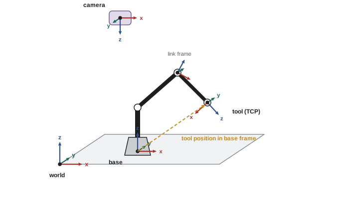
In ROS 2 the conventional names for mobile robots come from REP 105: map for the global frame, odom for a smooth but drifting odometry frame, and base_link attached to the robot body. Arms add a frame per link, and the tf2 library, covered in ROB-110, keeps track of all the transforms between them as they change over time. This course supplies the mathematics that tf2 performs internally.
Notation: who is described relative to whom
Because every coordinate is relative to a frame, good notation records the frame. This course follows the convention used by Craig and by Lynch and Park, with a leading superscript for the frame in which a quantity is expressed. The position of point P expressed in frame A is written \( {}^{A}\mathbf{p} \). The position of the origin of frame B, expressed in frame A, is \( {}^{A}\mathbf{p}_{B} \). In the next lessons we write the rotation that describes frame B's orientation relative to A as \( {}^{A}R_{B} \) and the full transform as \( {}^{A}T_{B} \).
The payoff of this notation is that frame labels cancel like units. A transform \( {}^{A}T_{B} \) takes coordinates in B and returns coordinates in A, so \( {}^{A}T_{B}\,{}^{B}\mathbf{p} = {}^{A}\mathbf{p} \). Chaining transforms works when the inner labels match: \( {}^{A}T_{B}\,{}^{B}T_{C} = {}^{A}T_{C} \). If you ever find yourself multiplying \( {}^{A}T_{B} \) by \( {}^{C}T_{D} \) with B and C different, the expression is wrong before you compute a single number. In code, the same discipline appears as variable names such as T_base_tool or p_cam, which make mismatches visible.
| Symbol | Meaning | Example |
|---|---|---|
| \( {}^{A}\mathbf{p} \) | Coordinates of a point, expressed in frame A | Object position seen by the camera: \( {}^{C}\mathbf{p} \) |
| \( {}^{A}\mathbf{p}_{B} \) | Origin of frame B expressed in frame A | Where the tool is relative to the base |
| \( {}^{A}R_{B} \) | Orientation of frame B relative to A (lesson 2) | Which way the gripper faces |
| \( {}^{A}T_{B} \) | Position and orientation of B relative to A (lesson 4) | Full pose of the camera on the wrist |
| \( \theta_i \), \( d_i \) | Joint variable of joint i: angle or displacement | Elbow angle \( \theta_3 \) |
| \( \mathbf{q} \) | Vector of all joint variables | \( \mathbf{q} = (\theta_1, \ldots, \theta_6) \) |
Changing frames by translation only
The simplest change of frame is a pure translation, where two frames have parallel axes but different origins. Then the coordinates of a point in frame A equal its coordinates in frame B plus the position of B's origin in A:
Note that this applies to points, not to free vectors. A displacement between two points is the difference of their positions, so the translation cancels: a vector has the same coordinates in two frames that differ only by translation. Once the frames are also rotated relative to each other, both points and vectors change, and we need the rotation matrices of the next lesson.
Worked problem
A sensor offset on a mobile base
A lidar is mounted on a robot with its axes parallel to base_link, 0.20 m forward and 0.35 m up from the base origin. It detects an obstacle at \( (2.10, -0.40, -0.25) \) m in the lidar frame. Where is the obstacle in the base frame, and how far is it from the base origin?
Show solution
- The lidar origin in the base frame is \( {}^{B}\mathbf{p}_{L} = (0.20, 0, 0.35) \).
- Add: \( {}^{B}\mathbf{p} = (2.10 + 0.20,\; -0.40 + 0,\; -0.25 + 0.35) = (2.30, -0.40, 0.10) \).
- Distance: \( \sqrt{2.30^2 + 0.40^2 + 0.10^2} = \sqrt{5.29 + 0.16 + 0.01} \approx 2.34 \) m.
Answer: The obstacle is at (2.30, −0.40, 0.10) m in base_link, about 2.34 m from the base origin. Getting the sign of a mounting offset wrong by a few centimetres is a classic source of collisions.
Degrees of freedom and configuration
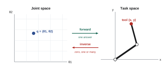
A rigid body moving freely in space has six degrees of freedom (DOF): three for position and three for orientation. A body confined to a plane has three: two for position and one for heading. The configuration of a robot is a complete specification of where every point of it is, and for a robot made of rigid links connected by joints, the configuration is captured by the joint variables. A revolute joint, marked R, rotates and is described by an angle; a prismatic joint, marked P, slides and is described by a displacement. The vector of all joint variables, \( \mathbf{q} \), lives in the joint space or configuration space of the robot.
The tool, in contrast, is described by its pose in the task space or Cartesian space: its position and orientation relative to the base. The central job of kinematics is to translate between the two spaces. Forward kinematics, lessons 5 to 7, computes the tool pose from the joint variables; it always has exactly one answer. Inverse kinematics, lessons 8 and 9, finds joint variables that produce a desired pose, and may have no answer, several answers or infinitely many. Velocity kinematics, lessons 10 and 11, relates joint speeds to tool speeds through the Jacobian matrix.
Grübler's formula, introduced in ROB-100, counts the degrees of freedom of a mechanism. For a serial chain where each joint adds one freedom, the robot's DOF equals its number of joints. A six-joint arm can therefore reach a general pose, position and orientation, within its workspace; a seven-joint arm has one degree of redundancy that can be used to avoid obstacles or joint limits; and a four-joint SCARA robot trades orientation freedom for speed and stiffness in pick-and-place work.
Computing with vectors in code
Throughout this course we use Python with NumPy to check calculations. Arrays of shape (3,) hold vectors; numpy.dot and numpy.cross implement the two products; and numpy.linalg.norm gives lengths. The listing below repeats the first worked example and computes a velocity from the cross product.
import numpy as np
a = np.array([0.0, 0.6, 0.8])   # camera axis
b = np.array([0.0, 0.0, 1.0])   # approach axis
cos_t = a @ b / (np.linalg.norm(a) * np.linalg.norm(b))
print(f"angle = {np.degrees(np.arccos(cos_t)):.1f} deg")
print("axis  =", np.cross(a, b))

# velocity of a point 0.5 m out along x on a body spinning at 2 rad/s about z
omega = np.array([0.0, 0.0, 2.0])
r = np.array([0.5, 0.0, 0.0])
print("v =", np.cross(omega, r), "m/s")angle = 36.9 deg axis = [0.6 0. 0. ] v = [0. 1. 0.] m/s
Worked problem
Speed of a gripper on a rotating base
A robot base rotates at 30 degrees per second about its vertical z-axis. The tool point is at \( (0.8, 0.2, 0.5) \) m in the base frame. What is the tool velocity due to this rotation alone?
Show solution
- Convert: \( 30^\circ/\text{s} = 0.5236 \) rad/s, so \( \boldsymbol{\omega} = (0, 0, 0.5236) \).
- Cross product: \( \boldsymbol{\omega} \times \mathbf{r} = (0 \cdot 0.5 - 0.5236 \cdot 0.2,\; 0.5236 \cdot 0.8 - 0 \cdot 0.5,\; 0) = (-0.105, 0.419, 0) \) m/s.
- Speed: \( \sqrt{0.105^2 + 0.419^2} \approx 0.432 \) m/s, which equals \( \omega \) times the horizontal distance \( \sqrt{0.8^2 + 0.2^2} = 0.825 \) m.
Answer: About (−0.105, 0.419, 0) m/s, a speed of 0.43 m/s. The height of the tool does not matter for rotation about a vertical axis, only its horizontal distance from the axis.
Units and angles
Kinematic formulas assume consistent units: metres or millimetres for lengths, radians for angles in calculations. Industrial controllers often display millimetres and degrees, ROS uses metres and radians (REP 103), and CAD files may be in inches. Convert at the boundary of your code and keep one system inside it. Remember that trigonometric functions in almost every programming language expect radians, and that a small error in an angle grows into a large position error at the end of a long arm: a 1-degree error at a shoulder joint moves a tool 1 m away by about 17 mm.
Common mistakes
MistakeTreating a point and a vector as interchangeable when changing frames.
InsteadPoints change under translation; free vectors such as velocities and directions do not.
MistakeUsing coordinates without stating the frame they are expressed in.
InsteadLabel every quantity with its frame, in notation and in variable names, and check that labels cancel.
MistakeMixing left-handed and right-handed conventions.
InsteadRobotics uses right-handed frames; check the conventions of every library, file format and sensor.
MistakeWriting \( \mathbf{b} \times \mathbf{a} \) when you mean \( \mathbf{a} \times \mathbf{b} \).
InsteadThe cross product changes sign when the order is reversed; apply the right-hand rule to check.
MistakePassing degrees to trigonometric functions.
InsteadConvert to radians at the boundary of your code and keep radians inside.
Summary and key terms
- Kinematics describes motion geometrically, without forces; dynamics adds forces later.
- Points mark locations; vectors are displacements with length and direction but no fixed location.
- The dot product gives angles and components; the cross product gives perpendicular directions, rotational velocities and torques.
- Robotics uses right-handed coordinate frames attached to the world, base, links, tools and sensors.
- Leading superscripts record the frame a quantity is expressed in, and frame labels cancel like units.
- A free rigid body has 6 DOF in space and 3 in the plane; a serial arm has one DOF per joint.
- Forward kinematics maps joint variables to tool pose uniquely; inverse kinematics may have many or no solutions.
- Kinematics
- The study of motion described by geometry and time, without reference to forces.
- Point
- A location in space with no size or direction.
- Vector
- A quantity with length and direction, such as a displacement or velocity.
- Dot product
- A scalar product equal to the product of lengths times the cosine of the angle between two vectors.
- Cross product
- A vector perpendicular to two vectors, with length equal to the area they span.
- Coordinate frame
- An origin and three perpendicular unit axes used to express coordinates.
- Tool centre point
- The working point of an end effector, where the tool frame is placed.
- Degrees of freedom
- The number of independent variables needed to specify a configuration.
- Joint space
- The space of all joint variable values of a robot.
- Task space
- The space of tool positions and orientations, usually relative to the base.
Practice problems
Work each problem on paper first, then reveal the answer to check.
Find the length of \( (3, 4, 12) \).
Show answer
\( \sqrt{9 + 16 + 144} = 13 \).
What is the unit vector in the direction of \( (3, 4, 12) \)?
Show answer
\( (3/13, 4/13, 12/13) \approx (0.231, 0.308, 0.923) \).
Compute \( (1, 2, 3) \cdot (4, -5, 6) \).
Show answer
\( 4 - 10 + 18 = 12 \).
Compute \( (1, 0, 0) \times (0, 1, 0) \).
Show answer
\( (0, 0, 1) \), the z-axis, as expected for a right-handed frame.
Two unit vectors have a dot product of 0.5. What is the angle between them?
Show answer
60°.
A camera is 0.1 m above and parallel to a gripper frame. A point is at \( (0, 0, 0.3) \) in the camera frame. Where is it in the gripper frame?
Show answer
\( (0, 0, 0.4) \) m.
How many DOF does a rigid body moving on a flat floor have?
Show answer
Three: x, y and heading.
A 7-joint arm controls a 6-DOF tool pose. How many redundant DOF does it have?
Show answer
One.
A body rotates at 1 rad/s about z. What is the velocity of the point \( (0, 2, 0) \)?
Show answer
\( (0,0,1) \times (0,2,0) = (-2, 0, 0) \) m/s.
A shoulder angle is off by 0.5°. Roughly how far is a tool 1.5 m away displaced?
Show answer
\( 1.5 \times 0.5 \times \pi/180 \approx 0.013 \) m, about 13 mm.
Lesson quiz · 5 questions
Score 60% or more to complete this lesson.
Create a free account to save your progress, take quizzes and earn a certificate.