
RAC-320 · Lesson 5 of 12 · 19 min
Inverter-driven and communicating systems
Mrs. Bauer chose the variable-speed heat pump. Her furnace was twenty years old too, so Northfield quoted a matched communicating system: a variable-speed outdoor heat pump, a variable-speed gas furnace with its own matched coil, and the manufacturer's communicating thermostat, all talking to each other over a two-wire data bus. Theo had wired single-stage systems with a thermostat cable and five or six colours of wire. This one used four wires for everything. "With these," Raj said as they unpacked the outdoor unit, "the old habits will mislead you. You can't put gauges on it, see the pressures move and adjust the charge the way you would on a single-stage unit, because the compressor's speed keeps changing under you. You have to work with the controls, not around them."
This lesson explains why capacity modulation matters, how inverter-driven compressors and the components around them work, how communicating systems differ from conventional thermostat wiring, and how technicians service them safely. RAC-130 introduced variable-frequency drives and electronically commutated motors; RAC-230 covered communicating controls and fault codes. Here the focus is on the equipment as a whole.
Single-stage, two-stage and variable-speed
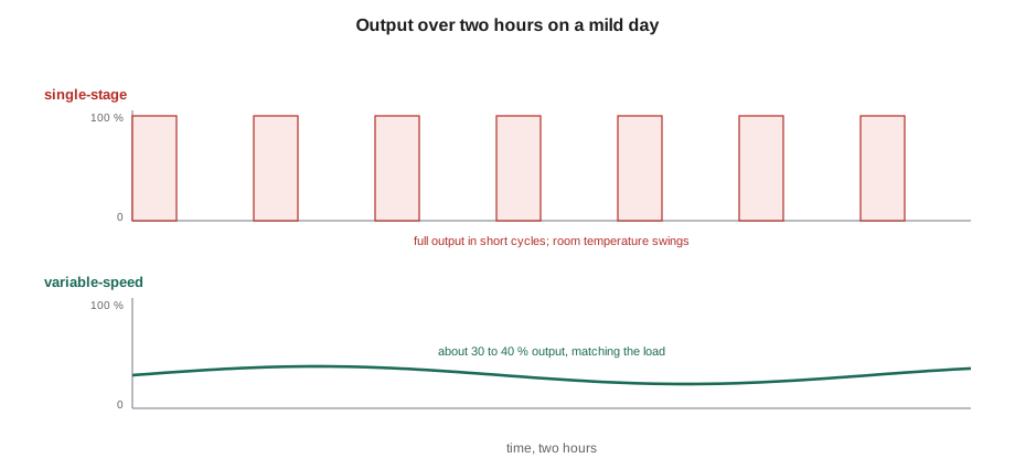
A single-stage unit has one capacity. When the thermostat calls, the compressor runs flat out; when the call ends, it stops. For most of the season the load is a fraction of the unit's capacity, so the unit cycles on and off, as lesson 7 shows for oversized equipment. Each start wastes energy: for the first few minutes, the refrigerant is redistributing, the coil is cooling down or warming up and the unit has not reached its rated efficiency. That loss is described by the cycling degradation coefficient, which the rating procedures include.
A two-stage unit has two capacities, usually about 65 to 70 % and 100 %, from a compressor with two speeds or an internal unloading mechanism. It runs on low stage most of the time and switches to high stage on hot or cold days.
A variable-speed unit, usually called an inverter unit, has a compressor driven by an inverter drive that varies its speed continuously, typically from about 25 or 30 % to 100 % or more of nominal capacity, and some cold-climate units well beyond 100 % in heating. It matches its output to the load and runs for long periods at low speed instead of cycling. Almost all ductless systems and the top tier of ducted systems are built this way.
Why low speed is efficient
At low speed, an inverter unit moves less refrigerant through coils that were sized for full capacity. The coils have more surface for the refrigerant flow, so the temperature differences across them shrink: the condenser runs cooler and the evaporator warmer. The compressor's lift falls, and so does the work it has to do for each unit of heat moved. That is why an inverter unit's efficiency at part load is often much better than at full load, the opposite of a single-stage unit, which loses efficiency at part load because of cycling.
There are limits. Below a certain speed, the compressor's own efficiency and oil return suffer, so manufacturers set a minimum speed, and when the load is below the unit's minimum capacity, the unit cycles at that minimum. Fans and the drive electronics use some power at all speeds. And at full speed an inverter unit may be no more efficient than a good single-speed unit, which is why EER2 values do not rise as much as SEER2 values across a product range.
The script below compares a season of cooling for a 2-ton single-stage unit and a 2-ton inverter unit of the same nominal size. The load in each outdoor temperature bin rises in a straight line from zero to the full 24,000 Btu/h at the design temperature. The single-stage unit's efficiency is cut by cycling at part load; the inverter unit's efficiency improves as it slows down, until it reaches its minimum speed. The efficiency curve is illustrative; real values come from the manufacturer's extended data.
# Seasonal cooling energy: single-stage cycling versus a variable-speed inverter unit
# Hours in each outdoor temperature bin during the cooling season (illustrative for Kitchener)
bins = {20: 300, 23: 260, 26: 200, 29: 110, 32: 40}
DESIGN_T, BAL_T = 32, 18        # load rises in a straight line from zero at BAL_T to full at DESIGN_T
FULL = 24000                       # Btu/h house cooling load at the design temperature
def load(t): return max(0.0, FULL * (t - BAL_T) / (DESIGN_T - BAL_T))
# single-stage unit: 24,000 Btu/h at an EER of 11.5, losing efficiency when it cycles (degradation coefficient 0.15)
def single(q):
    x = q / 24000
    return q / 11.5 / (1 - 0.15 * (1 - x))
# inverter unit: modulates from 30 % to 110 % of 24,000 Btu/h; efficiency is best at low speed (illustrative curve)
def inverter(q):
    x = max(q / 24000, 0.30)
    eer = 11.0 + 9.0 * (1 - x)           # 11 EER at full speed, about 17 at 30 %
    w = (x * 24000) / eer
    return w * (q / (x * 24000))       # below the minimum speed it cycles at the low-speed efficiency
e1 = sum(single(load(t)) * h for t, h in bins.items()) / 1000
e2 = sum(inverter(load(t)) * h for t, h in bins.items()) / 1000
print(f"single-stage {e1:,.0f} kWh, inverter {e2:,.0f} kWh, saving {100 * (1 - e2 / e1):.0f} %")
for t, h in bins.items():
print(f" {t:4.0f} °C bin, {h:4d} h: load {load(t):6.0f} Btu/h ({load(t) / 24000:4.0%} of full)")single-stage 842 kWh, inverter 625 kWh, saving 26 %
20 °C bin, 300 h: load 3429 Btu/h ( 14% of full)
23 °C bin, 260 h: load 8571 Btu/h ( 36% of full)
26 °C bin, 200 h: load 13714 Btu/h ( 57% of full)
29 °C bin, 110 h: load 18857 Btu/h ( 79% of full)
32 °C bin, 40 h: load 24000 Btu/h (100% of full)In Kitchener's short season the inverter unit saves about a quarter of the cooling energy, close to 220 kWh a year. The listing below the totals shows why: most of the season's hours are in bins where the load is a third of full capacity or less, exactly where the single-stage unit cycles most and the inverter unit is most efficient. In heating, the advantage is larger still, because an inverter heat pump can also speed up beyond its nominal capacity on cold days, which pushes the balance point down.
Comfort and humidity
Customers notice inverter systems for their comfort as much as their bills. Long, slow run cycles keep temperatures within a fraction of a degree, remove the blasts of cold or warm air at the start of each cycle and make the system quieter. In cooling, low speed and low airflow keep the indoor coil cold and wet for long periods, which removes more moisture. Many communicating systems have a dehumidification mode that slows the blower further when indoor humidity is high, at the cost of some sensible capacity. In humid summers that can make a house feel much more comfortable at the same thermostat setting.
Poorly set up inverter systems can lose that advantage. If the blower is set too high, or the system's humidity control is off, an inverter unit can run long cycles at low speed with a coil too warm to dehumidify. Matching the airflow and dehumidification settings to the climate and the house is part of commissioning, as lesson 10 explains.
Inside an inverter outdoor unit
An inverter outdoor unit has more electronics than refrigeration in its control box. Incoming alternating current passes through a filter that keeps electrical noise out of the supply, then a rectifier that turns it into direct current, which charges large capacitors on the DC bus. An intelligent power module, a set of fast switching transistors, chops the DC into variable-frequency, variable-voltage power for the compressor motor, usually a brushless permanent-magnet motor. Many units also correct the power factor so that the current drawn from the supply is close to a clean sine wave. The outdoor fan is usually a DC electronically commutated motor run from the same board.
The controller reads a set of temperature sensors, typically outdoor air, outdoor coil, discharge line, suction line and sometimes the heat sink of the power module, and pressure transducers on some models. It sets the compressor speed, the fan speed and the electronic expansion valve position from these readings and from the demand sent by the indoor unit or thermostat. When a sensor reads out of range, the controller logs a fault and either runs a protective mode or stops.
The control box is dangerous after the power is switched off. The DC bus capacitors hold several hundred volts for minutes after the disconnect is opened, and the board's discharge circuit may have failed. Manufacturers' service manuals show where to measure the bus voltage and say how long to wait. The rule Raj taught Theo was simple: open the disconnect, wait the time the manual gives, then measure the DC bus at the points the manual shows with a meter rated for the voltage, and only then touch anything inside, as RAC-130 described for drives.
Communicating systems
In a conventional system the thermostat closes simple switches: R to Y for cooling, R to W for heat, R to G for the fan, R to O or B for the reversing valve, as RAC-230 explained. The equipment knows only that a call is on or off. In a communicating system, the thermostat, the indoor unit and the outdoor unit exchange digital messages over a two- or four-wire bus. The thermostat sends a demand as a percentage, and the equipment reports its status, its sensor readings and its faults back.
That has several consequences for technicians.
- Set-up is done in the thermostat or the indoor control's menus: equipment sizes, airflow settings, the heat pump's lockout and balance point, the dehumidification settings and the backup heat's staging. A communicating system installed without going through those menus often runs on defaults that do not suit the house.
- Faults are logged with codes, times and sometimes sensor readings. Reading the fault history first saves a lot of time; a fault that occurred twenty times last week tells a different story from one that occurred once.
- Equipment from different manufacturers, or even different product lines of the same manufacturer, often cannot communicate. Many communicating units can also run on conventional thermostat wiring, but some features are then lost.
- Wiring faults look different. A shorted, open or reversed data pair can stop the whole system, as the Lindqvists' bus fault from a renovation staple showed in RAC-230. Manufacturers give the bus voltage to expect between terminals and the polarity.
Charging and testing inverter equipment
An inverter unit's pressures, superheat and subcooling change with compressor speed, so charging and performance checks must be done at a fixed, known speed. Every manufacturer provides a way to do that: a charge or test mode, selected at the outdoor board or through the thermostat, that runs the compressor at a set speed and the fans at set speeds for a period. Charging procedures then compare the readings with the manufacturer's tables for that mode, often a subcooling target at the liquid line, as RAC-220 described. On many ductless units the procedure is simpler: the charge is weighed in exactly for the line length, and the system is not charged by pressures at all.
Some inverter units also report their own refrigerant readings: suction and discharge pressures from transducers, superheat calculated by the controller, the electronic valve position and compressor speed. Those readings are useful, but sensors can drift. When a reading is surprising, a technician confirms it with gauges and a probe before acting on it.
Diagnosing inverter faults
When an inverter system stops with a fault, the work is usually methodical rather than intuitive. Raj's sequence was the same on every brand. First, read and record the fault code and the history, and look it up in the service manual for that model; codes are not standard between manufacturers. Second, check the supply: voltage at the outdoor unit, the disconnect and fuses, and the interconnect or bus voltages. Third, check the sensors the code points to by measuring their resistance and comparing it with the manual's table at the measured temperature, as RAC-230 showed for thermistors. Fourth, check the compressor windings with the drive disconnected: the three windings of a brushless compressor should have equal, low resistance, and none should be shorted to ground. Fifth, and only after the others, consider the board.
Boards fail, but they are expensive and often blamed for faults elsewhere. A compressor with a shorted winding destroys a new board within seconds, so the compressor check must come before a board is replaced. Insulation resistance tests on compressor windings must be done with the compressor's leads disconnected from the drive; a megohmmeter applied with the drive connected can damage its transistors. Surge protection on the outdoor unit's supply is cheap insurance against the voltage spikes that damage drives, and Northfield fitted one on every inverter installation.
Common mistakes
MistakeCharging an inverter unit while its compressor speed is changing.
InsteadPut it in the manufacturer's charge or test mode, or weigh the charge in.
MistakeTouching the inverter board soon after opening the disconnect.
InsteadWait the time in the manual and measure the DC bus first.
MistakeReplacing a board before checking the compressor windings.
InsteadCheck the windings with the drive disconnected; a shorted compressor kills a new board.
MistakeLeaving a communicating system on its default settings.
InsteadSet airflow, heat pump lockouts, staging and dehumidification for the house.
MistakeMegging a compressor with the drive still connected.
InsteadDisconnect the compressor leads from the drive first.
Summary and key terms
- Single-stage units cycle at full output; two-stage units have two outputs; inverter units vary their speed continuously.
- Inverter units are most efficient at low speed, because the coils' temperature differences and the compressor's lift shrink.
- Long, slow cycles improve comfort and, with correct settings, humidity removal.
- Inverter outdoor units have a rectifier, a DC bus, a power module and many sensors; the bus stays charged after power is removed.
- Communicating systems exchange digital messages, are set up in menus and log faults.
- Charge and test inverter units in the manufacturer's fixed-speed mode, and diagnose faults methodically before blaming the board.
- Inverter
- An electronic drive that converts AC to DC and back to variable-frequency AC to vary a motor's speed.
- DC bus
- The direct-current link inside an inverter drive, held up by large capacitors.
- Intelligent power module
- The switching transistors and their driver circuits that produce the compressor's variable-frequency supply.
- Cycling degradation coefficient
- A measure of the efficiency a unit loses by starting and stopping.
- Communicating system
- Equipment and a thermostat that exchange digital data over a bus instead of simple on-off signals.
- Charge mode
- A manufacturer's test mode that runs an inverter unit at fixed speeds for charging and checking.
- Two-stage unit
- Equipment with two fixed capacity levels.
Practice problems
Work each problem on paper first, then reveal the answer to check.
Why does an inverter unit become more efficient as it slows down?
Show answer
The coils are large for the reduced flow, so condensing temperature falls, evaporating temperature rises and the compressor's lift shrinks.
What must be done before measuring superheat on an inverter heat pump?
Show answer
Run it in the manufacturer's charge or test mode at a fixed speed.
An inverter outdoor unit shows a compressor fault. What should be checked before the board is replaced?
Show answer
The supply, the sensors the code points to and the compressor windings, with the drive disconnected.
Name two things a communicating thermostat lets a technician set that a conventional thermostat may not.
Show answer
Any two of: airflow, heat pump lockout or balance point, backup heat staging, dehumidification settings, equipment sizes.
Lesson quiz · 5 questions
Score 60% or more to complete this lesson.
Create a free account to save your progress, take quizzes and earn a certificate.