
PHYS-131 · Lesson 6 of 12 · 33 min
Circuit analysis, measurement and batteries
Lesson 5 introduced current, resistance, Ohm's law, series and parallel resistors and Kirchhoff's laws. With those tools any resistive circuit can be solved, but larger circuits need a system, and practical work raises new questions. What does a sensor connected to a long cable actually deliver to the instrument reading it? Does connecting a meter change the very voltage it is measuring? How do engineers measure a strain of a few millionths with a resistor? How long will a battery run a device, and why does its voltage sag under load? This lesson develops nodal analysis for systematic solution, the Thévenin and Norton equivalents that reduce any network to a simple source, the maximum power transfer theorem, the principles and pitfalls of meters, the Wheatstone bridge and strain gauge, and the practical behaviour of batteries. ELE-202 and ENCM courses take circuit analysis much further.
Nodal analysis
For circuits with more than a few loops, applying Kirchhoff's laws ad hoc becomes error-prone. Nodal analysis organizes the work. Choose one node as the reference (ground, 0 V) and label the voltages of the other nodes as unknowns. At each unknown node, write Kirchhoff's current law: the sum of currents leaving through all connected branches is zero, with each resistor current written as (voltage difference)/R from Ohm's law. The result is one linear equation per node, a system that MATH-125 methods solve by hand for two or three nodes and that computers solve for millions in circuit simulators.
Worked problem
A two-node circuit
A 12 V source is connected through 2 Ω to node 1. Node 1 connects to ground through 4 Ω and to node 2 through 3 Ω; node 2 connects to ground through 6 Ω. Find the node voltages.
Show solution
- KCL at node 1: \(\dfrac{V_1 - 12}{2} + \dfrac{V_1}{4} + \dfrac{V_1 - V_2}{3} = 0\), or \(13V_1 - 4V_2 = 72\) after multiplying by 12.
- KCL at node 2: \(\dfrac{V_2 - V_1}{3} + \dfrac{V_2}{6} = 0\), so \(V_1 = 1.5V_2\).
- Substituting: \(19.5V_2 - 4V_2 = 72\), \(V_2 = 4.645\) V and \(V_1 = 6.97\) V.
Answer: V₁ = 6.97 V and V₂ = 4.65 V. Checking: the source current (12 − 6.97)/2 = 2.52 A equals the sum of the currents 6.97/4 = 1.74 A to ground and (6.97 − 4.65)/3 = 0.77 A onward. ✓
Thévenin and Norton equivalents
Seen from any two terminals, a linear network of sources and resistors behaves exactly like a single voltage source \(V_{Th}\) in series with a single resistance \(R_{Th}\) (Thévenin's theorem), or equivalently a current source \(I_N = V_{Th}/R_{Th}\) in parallel with \(R_{Th}\) (Norton's theorem). This is enormously useful: a complicated sensor circuit, a battery pack or an amplifier output can be summarized by two numbers, and then any load connected to it is a simple series circuit.
To find the equivalent: \(V_{Th}\) is the open-circuit voltage at the terminals; \(R_{Th}\) is the resistance seen looking back into the terminals with the independent sources turned off (voltage sources replaced by short circuits, current sources by open circuits), or equivalently \(V_{Th}\) divided by the short-circuit current. A network can also be reduced step by step, replacing each source and its resistors by a Thévenin equivalent and combining.
Worked problem
Reducing a network
Add a 1 Ω resistor from node 2 of the previous circuit to an output terminal. Find the Thévenin equivalent at the output.
Show solution
- The 12 V source with its 2 Ω, seen across the 4 Ω, is a divider: \(V = 12 \times 4/6 = 8\) V behind \(2 \parallel 4 = 1.33\) Ω.
- Add the 3 Ω in series: 8 V behind 4.33 Ω. Across the 6 Ω: \(V = 8 \times 6/10.33 = 4.65\) V behind \(4.33 \parallel 6 = 2.52\) Ω.
- Add the 1 Ω in series: \(V_{Th} = 4.65\) V, \(R_{Th} = 3.52\) Ω.
Answer: The whole network acts as a 4.65 V source with 3.52 Ω internal resistance. A 10 Ω load would draw 4.65/13.52 = 0.34 A and see 3.44 V, found without re-solving the network.
import numpy as np

# Network: 12 V source with 2 ohm to node 1; 4 ohm node 1 to ground; 3 ohm node 1 to node 2;
# 6 ohm node 2 to ground; 1 ohm node 2 to node 3 (output terminal); load RL from node 3 to ground.
Vs = 12.0

def solve(RL):
    G = np.zeros((3, 3)); I = np.zeros(3)
    def add(a, b, R):                      # conductance between nodes a and b (-1 = ground)
        g = 1 / R
        for n in (a, b):
            if n >= 0: G[n, n] += g
        if a >= 0 and b >= 0:
            G[a, b] -= g; G[b, a] -= g
    add(0, -1, 2.0); I[0] += Vs / 2.0       # source as a Norton equivalent: 12 V behind 2 ohm
    add(0, -1, 4.0); add(0, 1, 3.0); add(1, -1, 6.0); add(1, 2, 1.0)
    if RL is not None:
        add(2, -1, RL)
    else:
        G[2, 2] += 1e-12                    # open circuit at the output
    return np.linalg.solve(G, I)

Voc = solve(None)[2]
Isc = solve(1e-9)[2] / 1e-9
Rth = Voc / Isc
print(f"Thevenin equivalent at the output: Vth = {Voc:.3f} V, Rth = {Rth:.3f} ohm")
for RL in [1.0, Rth, 10.0]:
    V = solve(RL)[2]
print(f"Load {RL:5.2f} ohm: voltage {V:.3f} V, power {V**2 / RL:.3f} W")Thevenin equivalent at the output: Vth = 4.645 V, Rth = 3.516 ohm Load 1.00 ohm: voltage 1.029 V, power 1.058 W Load 3.52 ohm: voltage 2.323 V, power 1.534 W Load 10.00 ohm: voltage 3.437 V, power 1.181 W
Maximum power transfer
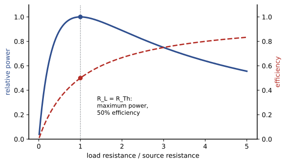
A source with internal resistance \(R_{Th}\) delivers power \(P = V_{Th}^2R_L/(R_{Th} + R_L)^2\) to a load \(R_L\). This is zero for a short circuit (no voltage) and for an open circuit (no current), and greatest in between. Setting \(dP/dR_L = 0\) gives the maximum power transfer theorem: the load receives the most power when \(R_L = R_{Th}\), and that power is \(V_{Th}^2/(4R_{Th})\). At this point, half the power is wasted in the source, so the efficiency is only 50%.
The code above confirms that the 3.52 Ω load draws more power (1.53 W) than either 1 Ω or 10 Ω. Matching is the right goal when signals are weak and every microwatt counts: antennas, radio receivers, audio amplifiers driving speakers, and the transmission lines of later courses are matched to their loads. It is the wrong goal for power systems, where efficiency matters most: a utility generator or a battery is operated with a load resistance far larger than its internal resistance, delivering power at high efficiency well below the theoretical maximum.
Meters and loading
An ammeter measures current, so it is placed in series with the branch, and it should have a very small resistance so that it does not change the current. A voltmeter measures the potential difference between two points, so it is connected in parallel, and it should have a very large resistance so that it draws negligible current. Modern digital multimeters typically have an input resistance of about 10 MΩ on voltage ranges. That is usually enough, but not always: connecting any meter changes the circuit it measures, an effect called loading.
Worked problem
A loading error
A divider made of two 1.0 MΩ resistors across a 10 V supply should give 5.0 V at its midpoint. What does a voltmeter with 10 MΩ input resistance read?
Show solution
- The meter appears in parallel with the lower resistor: \(1.0 \parallel 10 = 0.909\) MΩ.
- Reading: \(10 \times 0.909/(1.0 + 0.909) = 4.76\) V.
Answer: The meter reads 4.76 V, almost 5% low, because its own resistance is not large compared with the circuit's. The rule of thumb: a voltmeter is accurate to about 1% only if its resistance is at least about 100 times the Thévenin resistance of the point being measured. High-impedance circuits such as pH probes and some sensors need electrometer-grade instruments.
Ammeters must never be connected across a voltage source: their low resistance makes a near short circuit, which blows the meter's fuse or worse. Clamp meters avoid breaking the circuit altogether by sensing the magnetic field around a conductor (Lesson 7), and are the standard tool for measuring currents in electrical installations.
The Wheatstone bridge and strain gauges
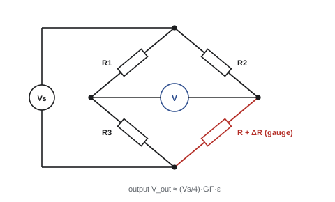
Some sensors change their resistance by tiny amounts. A strain gauge, a thin foil grid bonded to a structure, changes resistance in proportion to the strain it experiences: \(\Delta R/R = GF \cdot \varepsilon\), with a gauge factor GF of about 2 for metal foil gauges. A strain of 500 microstrain (5 × 10⁻⁴), a typical working strain in steel, changes a 350 Ω gauge by only 0.35 Ω. Measuring such a small change directly is hopeless; the Wheatstone bridge makes it easy.
A bridge has four resistors in a diamond, with a supply across one diagonal and a voltmeter across the other. When the ratios of the two halves are equal, the bridge is balanced and the output is zero; a small change in one arm produces a small output voltage that can be amplified, starting from zero rather than from a large background voltage. With one active gauge (a quarter bridge) and supply \(V_s\), the output is approximately
Worked problem
Measuring strain in a bridge girder
A quarter-bridge circuit with a 5.0 V supply uses a gauge with GF = 2.1. What output corresponds to a strain of 500 microstrain, and what stress is that in steel (E = 200 GPa)?
Show solution
- \(V_{out} \approx (5.0/4) \times 2.1 \times 5 \times 10^{-4} = 1.31\) mV.
- Stress: \(\sigma = E\varepsilon = 200\,000 \times 5 \times 10^{-4} = 100\) MPa (PHYS-130).
Answer: About 1.3 mV for 100 MPa, so the instrument must resolve microvolts. Practical systems use half or full bridges with several active gauges, which multiply the output and cancel the effect of temperature on the gauges, a key source of error. Strain gauges monitor bridges, aircraft, pipelines and load cells in weighing scales.
Batteries in practice
A real battery behaves approximately as an ideal emf in series with an internal resistance (Lesson 5), so its terminal voltage sags as current increases and recovers when the load is removed. Its capacity is stated in ampere-hours (Ah): a 100 Ah battery can in principle supply 5 A for 20 hours. The energy it stores is capacity times average voltage, in watt-hours. Currents are often expressed as a C-rate: 1C discharges the battery in one hour, 0.5C in two.
Real capacity depends on how the battery is used. Lead-acid batteries deliver noticeably less than their rated capacity at high currents (Peukert's effect) and should not be discharged below about half capacity if they are to last; lithium-ion batteries hold their capacity better at high rates and tolerate deeper discharge, but lose capacity in the cold, a significant effect in Canadian winters and northern US states. Capacity also fades over hundreds to thousands of charge cycles.
Worked problem
Sizing a backup battery
A remote monitoring station draws 18 W from a 12 V battery. It must run for 3 days without sun. What lithium iron phosphate battery capacity is needed if 80% of the capacity can be used, and what lead-acid capacity if only 50% can?
Show solution
- Energy: 18 W × 72 h = 1296 Wh. Current: 18/12 = 1.5 A, so 1.5 × 72 = 108 Ah.
- Lithium iron phosphate: 108/0.8 = 135 Ah.
- Lead-acid: 108/0.5 = 216 Ah.
Answer: About 135 Ah of lithium iron phosphate or 216 Ah of lead-acid, before allowing for cold weather and ageing, which typically add another 20 to 50%. The lithium battery also weighs perhaps a third as much, which matters when equipment is flown to a remote site.
Common mistakes
MistakeMixing sign conventions within a nodal equation.
InsteadWrite every current as leaving the node: (V_node − V_other)/R.
MistakeFinding R_Th with the sources still active.
InsteadShort voltage sources and open current sources, or use V_oc/I_sc.
MistakeDesigning power systems for maximum power transfer.
InsteadMaximum power transfer gives only 50% efficiency; power systems use loads much larger than R_Th.
MistakeIgnoring meter loading in high-resistance circuits.
InsteadA voltmeter needs a resistance at least about 100 times the circuit's Thévenin resistance.
MistakeSizing a battery on its full rated capacity.
InsteadAllow for usable depth of discharge, temperature and ageing.
Summary and key terms
- Nodal analysis writes KCL at each node with resistor currents (V_a − V_b)/R.
- Any linear two-terminal network has a Thévenin equivalent V_Th in series with R_Th, or a Norton equivalent.
- Maximum power is delivered when R_L = R_Th, at 50% efficiency.
- Ammeters go in series with low resistance; voltmeters in parallel with high resistance.
- Meter loading causes errors when the meter resistance is not much larger than the circuit's.
- Strain gauges change resistance by GF·ε; a quarter bridge gives V_out ≈ (V_s/4)GF·ε.
- Battery capacity in Ah, energy in Wh; usable capacity depends on chemistry, depth of discharge, temperature and age.
- Node
- A point in a circuit where two or more elements connect.
- Nodal analysis
- Solving a circuit by writing Kirchhoff's current law at each node.
- Thévenin equivalent
- A voltage source in series with a resistance that represents a network at two terminals.
- Norton equivalent
- A current source in parallel with a resistance that represents a network.
- Maximum power transfer
- The condition R_L = R_Th for greatest load power.
- Loading
- The change in a circuit caused by connecting a meter or load.
- Wheatstone bridge
- A four-arm resistor circuit for measuring small resistance changes.
- Strain gauge
- A resistor whose resistance changes in proportion to strain.
- Gauge factor
- The ratio of fractional resistance change to strain.
- C-rate
- Battery current expressed relative to the current that would discharge it in one hour.
Practice problems
Work each problem on paper first, then reveal the answer to check.
Write the KCL equation at node A connected to 10 V through 5 Ω and to ground through 10 Ω, and solve.
Show answer
(V − 10)/5 + V/10 = 0: V = 6.67 V.
A 9 V source has 3 Ω internal resistance. Find the load current and voltage for a 6 Ω load.
Show answer
1 A and 6 V.
Find the Thévenin equivalent of 24 V in series with 6 Ω, with 12 Ω across the terminals.
Show answer
V_Th = 16 V, R_Th = 4 Ω.
What load gets maximum power from that equivalent, and how much?
Show answer
4 Ω; 16²/(4 × 4) = 16 W.
Find the Norton current for V_Th = 10 V, R_Th = 2 Ω.
Show answer
5 A.
A 10 MΩ voltmeter measures across 100 kΩ in a divider of two 100 kΩ resistors from 10 V. What does it read?
Show answer
100 k ∥ 10 M = 99.0 k: reading 4.98 V (0.5% low).
A 120 Ω gauge (GF 2.0) sees 1000 µε. Find ΔR.
Show answer
0.24 Ω.
Find the quarter-bridge output for that strain with a 10 V supply.
Show answer
(10/4) × 2 × 0.001 = 5 mV.
A 50 Ah battery supplies 10 A. What is the C-rate and nominal run time?
Show answer
0.2C; 5 h.
How many watt-hours does a 3.6 V, 3000 mAh phone cell store?
Show answer
10.8 Wh.
Lesson quiz · 5 questions
Score 60% or more to complete this lesson.
Create a free account to save your progress, take quizzes and earn a certificate.