
PET-440 · Lesson 11 of 12 · 19 min
Pipelines, compression and LNG
Residue gas leaves the Caribou Ridge gas plant at about 4,500 kPa (650 psia). To reach the sales point at Station 2 it must travel about 68 km (42 miles) by pipeline and arrive above the transmission system's receipt pressure of about 5,500 kPa (800 psia). Sofia owns the sales line design, and she asks Ethan to work through the flow equations with her. “The reservoir decides how much gas you have,” she says. “The pipeline decides how much you can sell on a cold day in January, when every customer wants it.” This lesson covers steady-state gas pipeline flow, design pressure under CSA Z662, compression, and the LNG export chain that now pulls on gas from both the Montney and its neighbours.
The general flow equation
Gas flowing in a pipeline loses pressure to friction, and because it expands as pressure falls, its velocity rises along the line. A steady-state energy balance for isothermal flow in a horizontal pipe, neglecting the small kinetic energy change, gives the general flow equation. In US customary units, with q_sc in scf/d, base temperature T_b in °R and base pressure p_b in psia, D the inside diameter in inches, L the length in miles, T_f the flowing temperature and z̄ the average z-factor:
The Fanning friction factor f, or its Darcy equivalent, depends on the Reynolds number and the pipe roughness. Because gas pipelines run at high Reynolds numbers, most flow is either partially turbulent, where f depends on the Reynolds number, or fully turbulent, where it depends only on roughness. The pressure-squared difference appears for the same reason as in the well inflow equation: the gas expands as it flows.
Before computers, engineers replaced the friction factor with simple correlations, giving the classic pipeline equations still found in tariffs and design manuals. The Weymouth equation (1912) uses f proportional to D^(−1/3) and is conservative for large-diameter, high-flow lines. The Panhandle A (1940s) and Panhandle B (1956) equations use friction factors that fall with Reynolds number and suit long transmission lines in partially turbulent flow. The AGA fully turbulent equation and the Colebrook-White equation solved iteratively are used for detailed design. A pipeline efficiency factor E, typically 0.90 to 0.95, absorbs bends, fittings, deposits and the difference between ideal and real pipe.
That is Panhandle B in US customary units, with q_sc in scf/d. Elevation changes add a hydrostatic term, important in hilly terrain such as the Appalachians or the foothills of the Rockies. Because pressure-squared falls linearly with distance in a uniform line, the pressure itself falls more steeply near the outlet, where the gas is less dense and moves faster.
# Sales pipeline from the plant: Weymouth and Panhandle B capacities, design pressure from Barlow's formula,
# and the compressor power to boost residue gas from plant outlet to pipeline pressure.
import math
SI = True      # True: metric units, False: oilfield units

gg, T_R, Z = 0.62, 60 + 459.67, 0.90           # residue gas gravity, flowing temperature, average z
Tb, pb = 520.0, 14.73                          # base conditions, deg R and psia
L_mi, D_in, E = 42.0, 19.25, 0.95               # length (miles), inside diameter (in), pipeline efficiency
p1, p2 = 1300.0, 800.0                          # inlet and outlet pressure, psia

def weymouth(p1, p2):
    return 433.5 * E * (Tb / pb) * ((p1 ** 2 - p2 ** 2) / (gg * T_R * L_mi * Z)) ** 0.5 * D_in ** 2.667 / 1e6

def panhandle_b(p1, p2):
    return 737.0 * E * (Tb / pb) ** 1.02 * ((p1 ** 2 - p2 ** 2) / (gg ** 0.961 * T_R * L_mi * Z)) ** 0.51 * D_in ** 2.53 / 1e6

qw, qp = weymouth(p1, p2), panhandle_b(p1, p2)
cv = 0.0283168                                  # 10^6 m3 per MMscf
print(f"Weymouth {qw * cv:.2f} x 10^6 m3/d, Panhandle B {qp * cv:.2f} x 10^6 m3/d" if SI else
      f"Weymouth {qw:,.0f} MMscf/d, Panhandle B {qp:,.0f} MMscf/d")
# pressure along the line at the Panhandle B rate: p(x)^2 = p1^2 - (p1^2 - p2^2) x / L
for frac in (0.0, 0.25, 0.5, 0.75, 1.0):
    p = math.sqrt(p1 ** 2 - (p1 ** 2 - p2 ** 2) * frac)
    print(f"  {frac * L_mi * 1.609:5.1f} km  {p / 0.145038:6,.0f} kPa" if SI else f"  {frac * L_mi:5.1f} mi  {p:6,.0f} psia")

# Barlow design pressure, NPS 20 pipe: OD 20 in, wall 0.375 in, grade X70 (SMYS 70,000 psi)
OD, t, S = 20.0, 0.375, 70000.0
F = 0.72 if not SI else 0.80                     # design factor: Class 1 under 49 CFR 192 / Class 1 under CSA Z662
P = 2 * S * t / OD * F                          # psig (joint and temperature factors 1.0)
print(f"Design pressure {P * 6.894757:,.0f} kPa with design factor {F:.2f} (CSA Z662 Class 1)" if SI else
      f"Design pressure {P:,.0f} psig with design factor {F:.2f} (49 CFR 192 Class 1)")

# Compressor: residue gas 125 MMscf/d from plant outlet 650 psia to 1,300 psia in two stages with intercooling to 80 F
k, Ts, eff, ps, pd, Zs = 1.28, 540.0, 0.78, 650.0, 1300.0, 0.92
q = 125e6                                       # scf/d of residue gas
r = (pd / ps) ** 0.5                            # equal ratio per stage
n = q / 379.5 / 86400                           # lb-mol/s
head = k / (k - 1) * Zs * 1545.35 * Ts * (r ** ((k - 1) / k) - 1)   # ft.lbf per lb-mol, adiabatic
hp = 2 * n * head / 550 / eff
Td = Ts * (1 + (r ** ((k - 1) / k) - 1) / eff) - 459.67
print(f"Ratio per stage {r:.2f}; discharge {(Td - 32) / 1.8:.0f} C before cooling; compressor power about {hp * 0.7457:,.0f} kW" if SI else
f"Ratio per stage {r:.2f}; discharge {Td:.0f} F before cooling; compressor power about {hp:,.0f} hp")Weymouth 10.18 x 10^6 m3/d, Panhandle B 12.84 x 10^6 m3/d
0.0 km 8,963 kPa
16.9 km 8,238 kPa
33.8 km 7,442 kPa
50.7 km 6,550 kPa
67.6 km 5,516 kPa
Design pressure 14,479 kPa with design factor 0.80 (CSA Z662 Class 1)
Ratio per stage 1.41; discharge 57 C before cooling; compressor power about 3,663 kW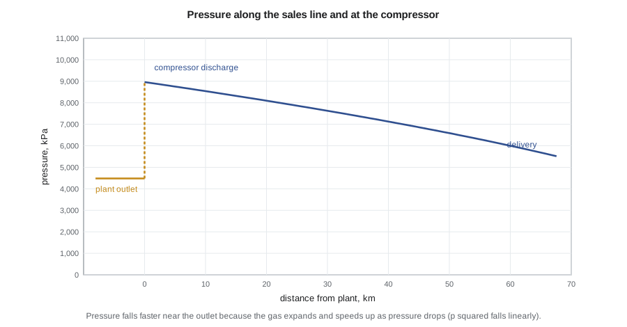
With an NPS 20 line, 19.25 inches (489 mm) inside diameter, a discharge pressure of 9,000 kPa (1,300 psia) and a delivery pressure of 5,500 kPa (800 psia), Panhandle B gives a capacity of about 12.8 × 10⁶ m³/d (450 MMscf/d) and Weymouth, the conservative choice, about 10.2 × 10⁶ m³/d (360 MMscf/d). Both far exceed the plant's initial 3.5 × 10⁶ m³/d (125 MMscf/d) of residue gas. Sofia explains the reasoning: pipe is cheap to oversize at construction and very expensive to loop later, and Prairie Crest expects to expand the plant or bring third-party gas into the line. At the initial throughput the line could run at a lower inlet pressure, saving compression.
Design pressure and pipeline codes
The wall thickness of a gas pipeline is set by Barlow's formula for hoop stress, with a design factor that depends on the population near the line. In Canada, CSA Z662, the Oil and gas pipeline systems standard, governs design, construction, operation and integrity management; its current edition is Z662:23, adopted by the BCER and the CER. The design pressure is P = (2St/D) × F × L × J × T, where S is the specified minimum yield strength, t the wall thickness, D the outside diameter, F the design factor of 0.8, L a location factor that depends on class location and service (1.0 for sweet gas in Class 1, lower for sour service or denser areas), J the joint factor and T the temperature factor. For the NPS 20 line with 9.5-mm wall in grade X70 steel, the design pressure is about 14,500 kPa (1,890 psig), well above the planned operating pressure.
Class location matters as much as the formula. As houses are built near a line over its life, its class location can change, lowering the allowed operating pressure unless the pipe is replaced or tested. Pipeline integrity management, with in-line inspection by smart pigs, cathodic protection, coating surveys, leak detection and damage prevention programs, keeps the line safe through its decades of service. The Caribou Ridge line's route avoids the few homes in the area and will be built for in-line inspection from the start.
Compression
Compressors raise gas pressure at the plant inlet when the field pressure falls, at the plant outlet to reach the sales line, and along transmission lines every 80 to 160 km (50 to 100 miles). Reciprocating compressors, driven by gas engines or electric motors, handle high ratios and variable conditions and dominate field and plant service. Centrifugal compressors, driven by gas turbines or motors, handle large volumes at modest ratios and dominate transmission. The power for adiabatic compression of a real gas from suction pressure p_s to discharge pressure p_d is:
per mole of gas, divided by the adiabatic efficiency, typically 0.75 to 0.85. Here k is the ratio of specific heats, about 1.25 to 1.3 for natural gas. The discharge temperature rises with the compression ratio, and practical limits on temperature and rod load keep reciprocating stages to ratios of about 3 to 4. Higher overall ratios use several stages with intercoolers between them, and equal ratios per stage minimize total power. For the Caribou Ridge gas plant's sales compressor, a two-stage machine with a ratio of about 1.4 per stage needs roughly 3,700 kW (4,900 hp) to move 3.5 × 10⁶ m³/d (125 MMscf/d), close to the rule of thumb of 1 kW per 10³ m³/d for an overall ratio of 2. Compressor fuel or electricity is one of the largest operating costs of a gas system, and electrifying compression, using power from the grid rather than gas engines, cuts emissions where clean grid power is available, as it is in much of British Columbia.
Worked problem
Pipeline capacity with the Weymouth equation
Estimate the Weymouth capacity of a 60-km NPS 16 line, 15.25 inches (387 mm) inside diameter, with inlet and outlet pressures of 8,270 and 5,510 kPa (1,200 and 800 psia), gas gravity 0.62, flowing temperature 520 °R, z̄ = 0.90 and E = 0.95. The Weymouth equation is q = 433.5 E (T_b/p_b)((p₁² − p₂²)/(γ T_f L z̄))^0.5 D^2.667, with T_b/p_b = 520/14.73 = 35.3 and q in scf/d.
Show solution
- p₁² − p₂² = 1,200² − 800² = 800,000 psi².
- γ T_f L z̄ = 0.62 × 520 × 37 × 0.90 = 10,736.
- Square-root term: (800,000 / 10,736)^0.5 = (74.5)^0.5 = 8.63.
- D^2.667 = 15.25^2.667 = 1,431.
- q = 433.5 × 0.95 × 35.3 × 8.63 × 1,431 = 180 × 10⁶ scf/d.
Answer: The line can carry about 180 MMscf/d (5.1 × 10⁶ m³/d) by Weymouth. Panhandle B would give roughly 20 percent more.
LNG: the export link
Liquefied natural gas connects North American gas to world markets. Gas is treated to remove carbon dioxide, water, mercury and heavy hydrocarbons, then cooled to about −162 °C in large refrigeration trains, at which point it condenses to a liquid about 1/600 of its gaseous volume. The liquid is stored in insulated tanks, loaded onto LNG carriers and regasified at the receiving terminal. Liquefaction uses roughly 8 to 12 percent of the feed gas as fuel, unless the trains are driven electrically.
Canada became an LNG exporter in 2025. LNG Canada at Kitimat, owned by Shell, Petronas, PetroChina, Mitsubishi and KOGAS, shipped its first cargo on June 30, 2025, from two trains with a combined capacity of 14 million tonnes per year. It is supplied through the Coastal GasLink pipeline, about 670 km long, from the Montney region of northeast British Columbia. In September 2026 the partners took a final investment decision on a second phase that would double capacity to 28 million tonnes per year, with five more compressor stations on Coastal GasLink and start-up expected in the early 2030s. The CER reported that Canada's marketable gas production reached a record of about 19 Bcf/d in 2025, with the Montney the dominant source of growth; LNG demand is the main reason its forecasts show Montney output continuing to rise.
For the Caribou Ridge plan, the LNG link matters through price and access. Gas sold at Station 2 on the Westcoast system, or delivered to the Alberta market, takes the regional price, which has historically traded at a discount to US benchmarks; LNG exports give western Canadian gas an outlet to Asian markets and are expected to narrow that discount over time. Lesson 12 uses a planning price that reflects these factors.
Common mistakes
MistakeDesigning a pipeline for today's flow only.
InsteadConsider future throughput; oversizing at construction is usually cheaper than looping later.
MistakeUsing the Weymouth equation for long transmission lines at moderate flow and accepting its capacity as exact.
InsteadWeymouth is conservative; compare with Panhandle B or a Colebrook-White calculation.
MistakeIgnoring class location changes over a pipeline's life.
InsteadMonitor population near the line; class changes can lower the allowed operating pressure.
MistakeChoosing a single high-ratio compressor stage.
InsteadUse several stages with intercooling; equal ratios minimize power and keep discharge temperatures safe.
Summary and key terms
- Gas pipeline flow depends on the difference of squared pressures because the gas expands along the line.
- Weymouth, Panhandle A and B and the general flow equation with Colebrook-White friction are standard design tools.
- Design pressure follows Barlow's formula with code design factors that depend on class location: CSA Z662 in Canada, 49 CFR 192 in the United States.
- Compressor power is set by flow, suction temperature and compression ratio; multistage compression with intercooling limits power and temperature.
- LNG liquefies gas at about −162 °C, reducing its volume about 600 times, and links North American gas to world markets.
- LNG Canada began exports in 2025; the United States is the world's largest LNG exporter.
- Weymouth equation
- A pipeline flow equation with a friction factor proportional to D^(−1/3), conservative for large lines.
- Panhandle B
- A pipeline flow equation suited to long transmission lines in partially turbulent flow.
- Barlow formula
- Hoop stress relation P = 2St/D used to set pipeline design pressure.
- Class location
- A classification of a pipeline segment by nearby population density, which sets its design factor.
- Compression ratio
- Discharge pressure divided by suction pressure, both absolute.
- LNG
- Liquefied natural gas, natural gas cooled to about −162 °C for transport by ship.
Practice problems
Work each problem on paper first, then reveal the answer to check.
If inlet and outlet pressures stay fixed and the line length doubles, by what factor does Weymouth capacity change?
Show answer
By 1/√2, about 0.71.
Why does pressure fall faster near the outlet of a gas pipeline?
Show answer
The gas expands as pressure falls, so velocity and friction loss per unit length increase.
What limits the compression ratio per stage of a reciprocating compressor?
Show answer
Discharge temperature and rod load; ratios of about 3 to 4 are typical.
Roughly how much smaller is LNG than the gas it came from?
Show answer
About 600 times smaller in volume.
Lesson quiz · 5 questions
Score 60% or more to complete this lesson.
Create a free account to save your progress, take quizzes and earn a certificate.