
PET-380 · Lesson 1 of 12 · 20 min
Multiphase flow in petroleum systems
Ethan Cardinal's second rotation at Prairie Crest Energy Ltd. takes him out of production engineering and into the facilities group in Calgary. His new mentor is Sofia Reyes, the senior facilities engineer who looks after the Tamarack Lake field gathering system. On his first morning she unrolls a large map across the table. A dozen thin lines run from well pads to the Tamarack battery, and a new dashed line runs 6.2 km south-west to the pad where the 04-22 well and two infill wells will be drilled next year. 'Your project for the next few months is that dashed line,' she says. 'We need to size it, check it will flow the whole life of the pad and make sure it never freezes, waxes up or slugs the battery off line. Everything you learned about nodal analysis stops at the wellhead. This is where it starts again.'
This course is about what happens when oil, gas and water flow together through pipes: up the tubing of a producing well, along flowlines and gathering lines, up risers and into separators. The physics of a single fluid in a pipe was covered in fluid mechanics. When two or three phases share the pipe, the gas and liquid travel at different speeds, arrange themselves into different flow patterns and exchange momentum at their interface. Pressure losses, liquid inventory, slugging and the risk of hydrates or wax all depend on these details. This first lesson describes where multiphase flow occurs in an oil and gas system, why it matters and how the rest of the course is organized.
Where multiphase flow occurs
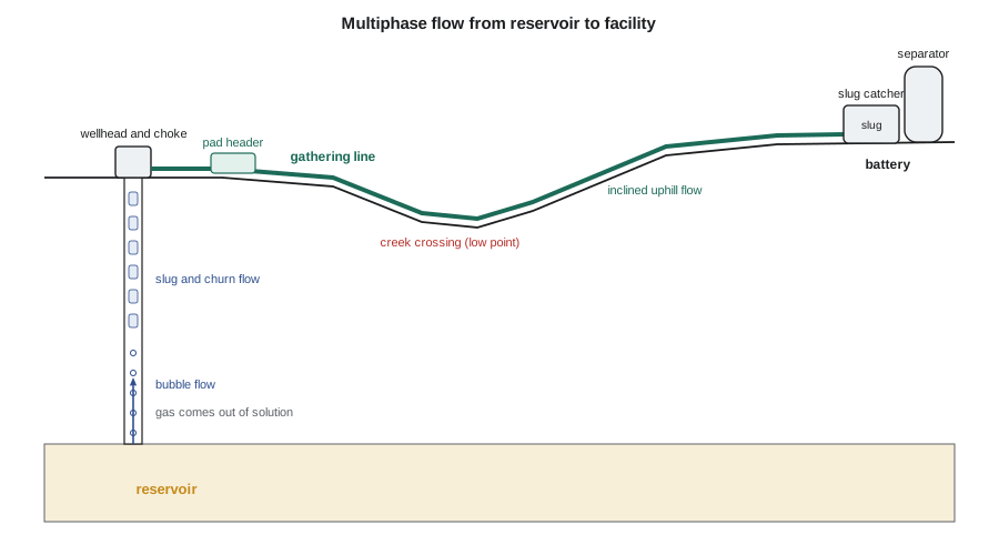
Almost every producing oil well flows more than one phase. Reservoir oil contains dissolved gas, and as the pressure falls below the bubble point on the way to surface that gas comes out of solution. Water is produced with the oil from most reservoirs and rises in proportion as a field matures. Gas wells produce condensate and water. Even a dry gas well produces water vapour that can condense in a cold line. As a result, the engineer meets two-phase or three-phase flow in five main places.
The first is the well itself. Fluid enters the wellbore from the reservoir, rises through the tubing, loses pressure to gravity and friction and changes its composition as gas comes out of solution. The vertical or deviated tubing is where flow pattern changes are most dramatic, and where most of the pressure is spent. The second is the surface flowline from the wellhead to a header or pad facility. The third is the gathering system, a network of lines that collects production from many pads and carries it to a battery, gas plant or compressor station. The fourth is the riser, the vertical or steep section that lifts fluid from a pipeline into a separator or from the seabed to a platform. The fifth is the processing facility itself, where separators, heaters and treaters split the stream back into its phases.
Why multiphase flow is harder than single-phase flow
In a single-phase line the designer needs the flow rate, the fluid density and viscosity, the pipe diameter and roughness and the elevation profile. A friction factor from the Moody chart then gives the pressure loss. In a multiphase line three new difficulties appear.
First, the phases slip. Gas is much lighter and less viscous than liquid, so in upward or horizontal flow it usually moves faster. The liquid lags behind and accumulates, so the fraction of the pipe filled with liquid, called the liquid holdup, is greater than the fraction of the flow that is liquid. Holdup controls the mixture density in the gravity term and the volume of liquid stored in the line.
Second, the phases arrange themselves into flow patterns. Gas can travel as small bubbles in a continuous liquid, as long bullet-shaped bubbles separated by liquid slugs, as a fast core with a liquid film on the wall, or as a separate layer above a liquid stream. Each pattern has its own friction, holdup and stability, so a model that works for one pattern can be badly wrong for another.
Third, the fluids change along the line. Pressure falls and temperature changes, so gas comes out of solution or condenses, water may condense from gas, and the in-situ volumes of each phase change. A calculation must therefore be done in steps, recomputing properties at each step, rather than once for the whole line.
The questions a multiphase design must answer
Sofia lists the questions Ethan's design must answer before the pipe is ordered. Will the line deliver the expected rates at a wellhead pressure the wells can provide, both in the first year when rates are high and late in life when they are low? How much liquid will sit in the line, and how much will arrive at the battery in one surge when the line is pigged or when flow restarts after a shut-in? Will the flow pattern be steady or slugging, and can the slug catcher handle the largest slugs? How cold will the fluid get in winter, and will it form hydrates or deposit wax? What corrosion and erosion allowances are needed, and what pressure rating and wall thickness does the code require?
Each question links to a lesson in this course. Lessons 2 and 3 review single-phase flow and define the multiphase variables. Lessons 4 and 5 describe flow patterns in horizontal, inclined and vertical pipes. Lesson 6 develops the homogeneous model and the three components of the pressure gradient. Lessons 7 and 8 cover the empirical correlations and mechanistic models used in practice. Lesson 9 applies them to pipeline and gathering system design. Lessons 10 and 11 deal with flow assurance: hydrates, wax, asphaltenes, slugging, liquid loading, corrosion and sand. Lesson 12 brings everything together in the design of the new tie-in.
Where the pressure goes
A useful first step in any gathering design is a pressure budget: a list of every place where pressure is lost between the wellhead and the separator. The separator pressure is set by the facility, which must deliver gas to a compressor or a sales line and oil to storage. The wells must supply that pressure plus every loss along the way. Any extra loss raises the required wellhead pressure, which raises the flowing bottomhole pressure and reduces the drawdown and the production rate. Late in a well's life, when reservoir pressure is low, a few hundred kilopascals can decide whether the well flows at all.
# Pressure budget for the new pad tie-in: where does the pressure go between wellhead and battery?
SI = True
# segment: (name, pressure loss in kPa)
segs = [("choke and wellhead piping", 260.0),
        ("pad header and meter run", 40.0),
        ("6.2 km gathering line, friction", 310.0),
        ("6.2 km gathering line, net elevation", 145.0),
        ("battery inlet and slug catcher", 35.0)]
p_battery = 700.0           # kPa gauge, inlet separator operating pressure
total = sum(dp for _, dp in segs)
p_wh = p_battery + total
f = 1.0 if SI else 0.145038
u = "kPa" if SI else "psi"
print(f"separator pressure at the battery: {p_battery * f:7.0f} {u}")
for name, dp in segs:
    print(f"  {name:38s} {dp * f:6.0f} {u}  ({dp / total:5.1%} of losses)")
print(f"required flowing wellhead pressure:  {p_wh * f:7.0f} {u}")
# every 100 kPa (about 15 psi) of extra back pressure at the wellhead costs production; PI-style estimate
pi = 0.9    # m3/d of liquid per 100 kPa of drawdown, illustrative near-wellbore sensitivity
for extra in (100.0, 200.0):
    loss = pi * extra / 100.0
    if SI: print(f"extra {extra:4.0f} kPa back pressure -> about {loss:.1f} m3/d less liquid")
else: print(f"extra {extra * f:4.0f} psi back pressure -> about {loss * 6.2898:.0f} bbl/d less liquid")separator pressure at the battery: 700 kPa choke and wellhead piping 260 kPa (32.9% of losses) pad header and meter run 40 kPa ( 5.1% of losses) 6.2 km gathering line, friction 310 kPa (39.2% of losses) 6.2 km gathering line, net elevation 145 kPa (18.4% of losses) battery inlet and slug catcher 35 kPa ( 4.4% of losses) required flowing wellhead pressure: 1490 kPa extra 100 kPa back pressure -> about 0.9 m3/d less liquid extra 200 kPa back pressure -> about 1.8 m3/d less liquid
Ethan's budget shows that the gathering line accounts for more than half of the losses between wellhead and separator, split between friction and the net climb of 32 m to the battery. The choke and wellhead piping take another third, and the rest is small. 'That is why we care about the line,' Sofia says. 'We cannot change the separator pressure, and the choke is there to control the well, but the line is ours to size. Every hundred kilopascals we save is production the wells keep.'
Typical numbers in a gathering system
Gathering lines in onshore fields are usually 3 to 12 inches in nominal diameter and from a few hundred metres to tens of kilometres long. Operating pressures range from a few hundred kilopascals in low-pressure oil gathering to several megapascals in gas gathering upstream of compression. Mixture velocities are typically 1 to 6 m/s (3 to 20 ft/s). Below about 1 m/s liquid tends to accumulate in low spots; above the erosional limit discussed in lesson 9, sand and droplets can wear the pipe. Liquid holdup in a horizontal oil gathering line is commonly 0.1 to 0.5, so a single kilometre of 6-inch line can hold several cubic metres of liquid.
| Part of the system | Main flow direction | Typical patterns | Main design concern |
|---|---|---|---|
| Tubing | Vertical or deviated upward | Bubble, slug, churn, annular | Bottomhole pressure, liquid loading |
| Flowline | Near horizontal | Stratified, slug | Back pressure on the well |
| Gathering line | Horizontal with hills and dips | Stratified, slug, terrain slugs | Pressure drop, inventory, slugs |
| Riser | Vertical upward | Slug, severe slugging | Unstable flow at the separator |
| Facility inlet | Into vessels | Whatever arrives | Slug catcher and separator capacity |
Regulation and codes
In Alberta, pipelines that carry oil, gas or produced water outside a facility are licensed by the Alberta Energy Regulator (AER) under the Pipeline Act and its regulations. The design, construction, operation and abandonment of most oil and gas pipelines must follow CSA Z662, the Canadian standard for oil and gas pipeline systems; its current edition is CSA Z662:23. The AER's Directive 056 sets out how to apply for a licence, and Directive 077 gives requirements and reference tools for pipelines. Lesson 9 returns to these rules when the line is sized and its wall thickness is chosen.
Worked problem
Reading a pressure budget
The separator at the battery operates at 700 kPa gauge. The choke and wellhead piping lose 260 kPa, the pad header 40 kPa, the line 455 kPa in friction and elevation and the battery inlet 35 kPa. What flowing wellhead pressure is needed, and what share of the losses is in the line?
Show solution
- Add the losses: 260 + 40 + 455 + 35 = 790 kPa.
- The wellhead must supply 700 + 790 = 1,490 kPa gauge.
- The line's share is 455 / 790 = 58 percent.
Answer: About 1,490 kPa gauge at the wellhead, with the gathering line taking nearly 60 percent of the losses.
A short history of the subject
Engineers have studied two-phase flow in pipes since the early days of steam power, when boiler tubes and steam lines carried water and vapour together. The petroleum industry took up the problem in earnest in the 1950s and 1960s, when gas lift design and long flowlines made pressure losses expensive to get wrong. The first methods were empirical: laboratory and field data were plotted against dimensionless groups, and curves were fitted for holdup and friction. Correlations from that period, such as those of Duns and Ros, Hagedorn and Brown, and Beggs and Brill, are still built into commercial software and still used for quick estimates.
From the 1970s onward, researchers developed mechanistic models that start from the physics of each flow pattern. Taitel and Dukler's work on flow pattern transitions, and later unified models from several university research programs, describe stratified, slug, bubble and annular flow with momentum and mass balances rather than curve fits. Since the 1990s, transient multiphase simulators have been used to study slugging, start-up, shut-in and pigging in long pipelines. A modern design team uses all three tools: quick correlations for screening, steady-state mechanistic models for design, and transient simulation for the cases where flow changes with time.
Sofia's advice to Ethan is practical. 'Learn what each method assumes,' she says. 'Software will give you an answer to four decimal places for any input. Your job is to know when that answer is believable, and that means knowing the flow pattern and what the model inside the box is doing.'
Common mistakes
MistakeTreating a gathering line as a single-phase liquid line.
InsteadGas and liquid slip and form patterns; use multiphase methods for holdup and pressure drop.
MistakeCalculating the whole line in one step.
InsteadProperties change with pressure and temperature; march along the line in segments.
MistakeIgnoring elevation because the ground looks flat.
InsteadA few tens of metres of net climb can be a large part of the loss, especially at low rates.
MistakeDesigning only for first-year rates.
InsteadCheck late-life rates too, when velocities are low and liquid accumulates.
Summary and key terms
- Multiphase flow occurs in tubing, flowlines, gathering lines, risers and facility inlets.
- Gas and liquid slip, so liquid holdup exceeds the input liquid fraction in most upward and horizontal flow.
- Flow patterns such as bubble, slug, annular and stratified flow each have their own friction and holdup.
- Fluid properties change along the line, so calculations march in segments.
- A pressure budget from wellhead to separator shows where pressure is lost and what the line costs the wells.
- Pipelines are licensed and built under provincial or state and federal rules and codes.
- Multiphase flow
- Simultaneous flow of gas, oil and water in the same pipe.
- Liquid holdup
- The fraction of a pipe segment occupied by liquid.
- Slip
- The difference in velocity between the gas and liquid phases.
- Flow pattern
- The spatial arrangement of gas and liquid in a pipe, such as slug or stratified flow.
- Gathering system
- The network of lines collecting production from wells and pads to a facility.
- Pressure budget
- A list of every pressure loss between the wellhead and the separator.
Practice problems
Work each problem on paper first, then reveal the answer to check.
Name the five places where multiphase flow commonly occurs.
Show answer
Tubing, flowlines, gathering lines, risers and facility inlets.
Why is holdup usually greater than the input liquid fraction in uphill flow?
Show answer
Gas moves faster than liquid, so liquid accumulates in the pipe.
Why must a multiphase line be calculated in segments?
Show answer
Pressure and temperature change, so phase volumes and properties change along the line.
Why does extra back pressure at the wellhead reduce production?
Show answer
It raises the flowing bottomhole pressure and reduces drawdown.
Lesson quiz · 5 questions
Score 60% or more to complete this lesson.
Create a free account to save your progress, take quizzes and earn a certificate.