
PET-340 · Lesson 7 of 12 · 20 min
Chokes, flowlines and surface pressure
Wes has been flowing the 04-22 through a 28/64 in choke bean since the well was opened, as the flowback plan specified. Ethan asks him why that size. 'It holds about 1,450 kPa on the wellhead and keeps the battery happy,' Wes says. 'When we opened it up to 32 during flowback, the separator flooded and the treater couldn't keep up.' Marisol uses the exchange to make a point: 'The choke is where the well meets the facilities. You need to understand it from both sides.'
This lesson covers what wellhead chokes do, the physics of critical and subcritical flow through a restriction, Gilbert's correlation and its relatives for multiphase choke flow, flowline pressure drop, erosional velocity, and how surface pressure affects the well and the field.
Why wells are choked
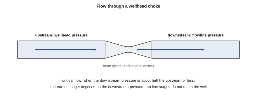
A choke is a deliberate restriction in the flow path, usually at the wellhead. It may be a positive choke, a fixed bean with a precisely sized bore that is changed by replacing it, or an adjustable choke, in which a needle or cage changes the open area. Bean sizes are traditionally given in sixty-fourths of an inch; a 32/64 choke has a half-inch bore.
Chokes serve several purposes. They control the rate of a flowing well, either to meet regulatory or contract limits, to protect the reservoir from excessive drawdown that might cause sand production, water or gas coning, or fines migration, or to match the capacity of the facilities. They protect downstream equipment by taking most of the pressure drop at one point designed for it, rather than in the flowline or separator. And in critical flow, described below, they isolate the well from pressure fluctuations in the gathering system, so that one well's behaviour does not disturb another's.
Choking also has a cost. Every kilopascal or psi taken across the choke is pressure that could have been used to produce more fluid. In flowing wells with spare pressure, choking is a reasonable way to manage rates; in wells near the edge of stability, a choke that holds too much backpressure can push the well onto the unstable side of its outflow curve. Once a well is on artificial lift, there is usually no production choke at all, and every bit of surface pressure is a direct penalty on the lift system.
Critical and subcritical flow
Flow through a restriction accelerates as the area narrows. For a gas, the velocity at the narrowest point cannot exceed the local speed of sound. Once that happens, further lowering the downstream pressure does not increase the rate, because pressure signals cannot travel upstream through a sonic throat. This is critical flow. For single-phase gas it occurs when the downstream pressure is below about 0.53 of the upstream absolute pressure; for gas-liquid mixtures the ratio is usually taken as about 0.5 to 0.6, depending on the gas fraction.
In critical flow, the rate through a choke depends only on upstream pressure, choke size and fluid properties. That makes chokes useful for metering and for isolating wells from the gathering system. In subcritical flow, the rate depends on both upstream and downstream pressures, and a change in line pressure, from a compressor trip or a slug arriving at the separator, travels straight back to the well.
Gilbert's correlation
Multiphase flow through chokes is too complex for simple theory, so engineers rely on correlations fitted to field data for critical flow. The best known is Gilbert's, published in 1954 from wells in California, which relates the wellhead pressure to the gross liquid rate, the gas-liquid ratio and the bean size.
Ros, Baxendell and Achong published similar correlations with different constants fitted to other fields. All of them apply only to critical flow and only to the range of data they were fitted to. They are useful for quick estimates, for checking choke settings and for spotting problems. A well whose wellhead pressure is much higher than the correlation predicts for its rate may have a partly plugged or eroded bean, or its gas-liquid ratio may have changed.
Rearranged, Gilbert's correlation gives the bean size needed to hold a target wellhead pressure at a given rate, which is how the program below uses it.
# Chokes and flowlines: Gilbert's choke correlation, the critical-flow check, and flowline velocity and erosion limits
import math
SI = True
if SI:   # 04-22 Cardium at month 1; field-unit correlation, results shown in SI
    q_l, glr, pwh, pdown = 66.0 * 6.2898, 85.0 * 5.6146 / 1000, 1450 * 0.145038, 700 * 0.145038
    cases_p = [1000, 1450, 2000]; to_p = lambda p: p * 0.145038; sp = lambda p: f"{p / 0.145038:6,.0f} kPa"
    line_id_in, line_len_ft, rho_m = 3.068, 1200 / 0.3048, 280.0      # 76 mm line, 1.2 km to the battery
else:    # 4-22H Bakken at month 1
    q_l, glr, pwh, pdown = 1610.0, 900.0 / 1610.0, 650.0, 300.0
    cases_p = [400, 650, 900]; to_p = lambda p: p; sp = lambda p: f"{p:6,.0f} psi"
    line_id_in, line_len_ft, rho_m = 3.068, 600.0, 16.0 * 16.018    # 3 in line, short line to the pad separator
def gilbert_size(q, R, p):      # bean size in 64ths of an inch
    return (435 * R ** 0.546 * q / p) ** (1 / 1.89)
if SI: print(f"gross liquid {q_l / 6.2898:,.0f} m3/d, gas-liquid ratio {glr * 1000 / 5.6146:,.0f} m3/m3")
else: print(f"gross liquid {q_l:,.0f} bbl/d, gas-liquid ratio {glr * 1000:,.0f} scf/bbl")
for pc in cases_p:
    p = to_p(pc); S = gilbert_size(q_l, glr, p)
    print(f"   to hold wellhead pressure {sp(p)} the choke is about {S:4.1f}/64 in ({S / 64 * 25.4:4.1f} mm)")
ratio = pdown / pwh
print(f"downstream/upstream pressure ratio {ratio:.2f}: {'critical flow, so the choke isolates the well from the line' if ratio < 0.55 else 'not critical, so line pressure changes reach the well'}")
# erosional velocity screen (API RP 14E form): ve = C / sqrt(rho_m) with C = 100 for continuous service (ft/s, lbm/ft3)
rho_lb = rho_m / 16.018
ve = 100 / math.sqrt(rho_lb)
A = math.pi * (line_id_in / 12) ** 2 / 4
q_ft3s = q_l * 5.6146 / 86400 * (1 + glr * 1000 * 0.06 / 5.6146)   # liquid plus in-line gas at line pressure (rough)
v = q_ft3s / A
if SI: print(f"flowline mixture velocity about {v * 0.3048:4.1f} m/s; erosional limit about {ve * 0.3048:4.1f} m/s ({v / ve:.0%} of the limit)")
else: print(f"flowline mixture velocity about {v:4.1f} ft/s; erosional limit about {ve:4.1f} ft/s ({v / ve:.0%} of the limit)")gross liquid 66 m3/d, gas-liquid ratio 85 m3/m3 to hold wellhead pressure 1,000 kPa the choke is about 35.1/64 in (13.9 mm) to hold wellhead pressure 1,450 kPa the choke is about 28.8/64 in (11.4 mm) to hold wellhead pressure 2,000 kPa the choke is about 24.3/64 in ( 9.6 mm) downstream/upstream pressure ratio 0.48: critical flow, so the choke isolates the well from the line flowline mixture velocity about 1.0 m/s; erosional limit about 7.3 m/s (13% of the limit)
For the 04-22 at about 66 m³/d of gross liquid and a gas-liquid ratio of about 85 m³/m³, Gilbert's correlation predicts that a bean of about 29/64 holds 1,450 kPa, close to the 28/64 Wes has in the well. Opening to about 35/64 would drop the wellhead pressure to about 1,000 kPa and, as lesson 6 showed, raise the rate, provided the battery can handle it. The pressure ratio across the choke is 0.48, so the flow is critical and line fluctuations do not reach the well.
Flowlines and gathering systems
From the choke, the fluid travels through a flowline to a battery or pad facility, and from there through gathering lines to a gas plant, oil terminal or pipeline. Flowline pressure drop has the same elevation and friction terms as tubing flow, but the elevation term depends on terrain rather than depth. In hilly country, liquid collects in low spots and the line may slug, with gas and liquid arriving at the separator in surges. Horizontal and inclined multiphase flow have their own flow patterns, including stratified and wavy flow, and their own correlations, such as Beggs and Brill, Dukler, and mechanistic models. PET-380 covers them.
For the production engineer, the key questions are usually simpler: whether the line is the right size for the well's rates, whether its pressure drop is a significant part of the system, and whether its velocities are within safe limits.
Erosion is the main velocity limit. Fast-moving fluid wears pipe walls, especially at bends, tees and chokes, and sand greatly accelerates the damage. A widely used screening rule from API RP 14E sets an erosional velocity as a constant divided by the square root of the mixture density, with a constant of about 100 in field units for continuous service in clean fluids. The rule is conservative for clean fluids and not conservative enough when sand is present, and modern practice uses sand erosion models from DNV and others where solids are produced. The program applies the simple screen.
The flowline from the 04-22 to the battery is a 76 mm line about 1.2 km long. The mixture velocity of about 1.0 m/s is only about 13 percent of the erosional screen, so the line is comfortably sized. Marisol notes that the bigger concern in winter is cold: the line is buried, but if it is shut in, waxy oil and water can gel or freeze, so the operators follow a cold-weather procedure that keeps the well flowing or flushes the line.
Surface pressure and the field
Every well in a gathering system shares the pressure downstream of its choke. A small, overloaded gathering system or a separator held at high pressure penalizes every well connected to it. Lowering the system pressure is one of the most effective ways to raise production from a mature field, particularly a gas field or a field of wells on artificial lift. The usual methods are adding compression, looping or replacing undersized lines, lowering separator pressures, and removing restrictions such as old meters and partly closed valves.
These field-wide improvements need a network model, which links each well's IPR and outflow curve to a model of the gathering system and finds the pressures and rates that satisfy every well and every pipe at once. Network models are standard tools in larger fields, where they are used to plan compression, tie in new wells and evaluate debottlenecking projects.
For the Tamarack Lake field, the battery separator runs at about 550 kPa, set by the sales gas line. Sofia Reyes, the facilities engineer, is studying whether a vapour recovery compressor at the battery could lower the separator pressure to about 300 kPa and recover tank vapours at the same time, a project that ties into the emissions work of lesson 11.
Worked problem
Checking a choke setting
A well produces 500 bbl/d of gross liquid with a gas-liquid ratio of 0.8 Mscf/bbl through a 24/64 in bean. Estimate the wellhead pressure in critical flow, and the downstream pressure below which the flow stays critical.
Show solution
- Gilbert: pwh = 435 × 0.8^0.546 × 500/24^1.89.
- 0.8^0.546 = 0.885; 24^1.89 = 405; so pwh = 435 × 0.885 × 500/405 = 475 psi.
- For critical flow, the downstream pressure should be below about 0.5 to 0.55 of the upstream absolute pressure, roughly 245 to 270 psi.
- If the separator runs at 300 psi, the flow is subcritical and Gilbert's correlation no longer applies.
Answer: Correlation results are estimates; a well's own history of rate, pressure and bean size is the best calibration.
Choke management in fractured wells
In multistage fractured wells, the choke has an extra job during the first weeks of production. Opening a new well hard creates a large, sudden drawdown across the fractures. That can crush or embed proppant near the wellbore, pull proppant back into the well, and close fractures as the stress on them rises. Many operators therefore follow a managed drawdown plan, opening the choke in steps over weeks or months and limiting the rate at which bottomhole pressure falls, for example to a set number of kilopascals or psi per day.
The evidence for managed drawdown is mixed and depends on the play. In some formations, operators report better long-term recovery and less proppant flowback; in others, the main effect is simply to delay production. The production engineer's job is to look at the field's own wells, compare those opened aggressively with those opened gently, and recommend a schedule that balances early cash flow against the risk of damaging the fractures. Because the choke schedule changes the early rate, it also changes when lift will be needed, so the two plans must be made together.
Sand and proppant returning with the fluid also wear chokes quickly. Field crews inspect beans regularly during flowback and replace them when the measured rate at a given pressure drifts upward, a sign that the bore is eroding.
Common mistakes
MistakeApplying Gilbert's correlation to subcritical flow.
InsteadCheck the pressure ratio first; the correlation assumes critical flow.
MistakeHolding high backpressure on a well near the edge of stability.
InsteadCheck nodal analysis; choking may push the well onto the unstable side.
MistakeIgnoring sand in erosional velocity checks.
InsteadUse sand erosion models when solids are produced.
MistakeChanging bean size without checking facility capacity.
InsteadConfirm that separators and treaters can handle the new rate.
MistakeTreating each well's backpressure in isolation.
InsteadConsider the gathering system; one bottleneck affects every well.
Summary and key terms
- Chokes control rate, protect equipment and, in critical flow, isolate wells from line fluctuations.
- Critical flow occurs when downstream pressure is below about half the upstream absolute pressure.
- Gilbert's correlation relates wellhead pressure, liquid rate, GLR and bean size in critical flow.
- Flowline pressure drop depends on terrain, rate and flow pattern.
- Erosional velocity screens protect pipe, but sand needs specific models.
- Lowering system pressure through compression and debottlenecking raises production across a field.
- Choke
- A restriction that controls flow rate, usually at the wellhead.
- Bean
- The replaceable orifice in a positive choke, sized in 64ths of an inch.
- Critical flow
- Flow in which the rate does not depend on downstream pressure because the throat is sonic.
- Gathering system
- The network of pipelines that collects production from wells and facilities.
- Erosional velocity
- A velocity limit intended to prevent erosion of pipe and fittings.
- Network model
- A model linking wells and pipelines to solve for field-wide pressures and rates.
Practice problems
Work each problem on paper first, then reveal the answer to check.
Why does critical flow isolate a well from its flowline?
Show answer
Pressure signals cannot travel upstream through a sonic throat.
A well's wellhead pressure is much higher than Gilbert predicts. Name a possible cause.
Show answer
A plugged bean or a change in gas-liquid ratio.
Why is surface pressure a direct penalty on artificial lift?
Show answer
The pump or gas must overcome it in addition to the fluid column.
What tool finds pressures and rates across a whole gathering system?
Show answer
A network model.
Lesson quiz · 5 questions
Score 60% or more to complete this lesson.
Create a free account to save your progress, take quizzes and earn a certificate.