
PET-340 · Lesson 1 of 12 · 20 min
The production system and the production engineer
The Tamarack 04-22 horizontal well came on production in the spring, and for its first weeks it flowed on its own: about 52 m³/d of oil, 14 m³/d of load and formation water and 5,600 m³/d of gas, all pushed to the Tamarack battery by reservoir pressure. Ethan Cardinal, the engineer-in-training who helped plan its drilling and completion, has now rotated into the production engineering group under Marisol Vega, a senior production engineer who has run wells in the Tamarack Lake field for fifteen years. On his first morning she hands him the well's test sheet. 'Completions made this well,' she says. 'Our job is to keep it producing as cheaply as possible for the next twenty years. Start by telling me where the reservoir's pressure goes.'
This course follows the 04-22 from its first weeks of natural flow, through the decision about when and how to add artificial lift, to a lift and optimization plan for its whole life. Along the way it uses the vertical 102/06-14 well, which was acidized in PET-330, and the 100/10-09 gas well in the Birch Coulee gas pool, which is starting to load up with water. This first lesson defines the production system, the production engineer's role, and the vocabulary of rates, ratios and pressures that the rest of the course uses.
What the production engineer does
Petroleum engineering divides the life of a well among several specialties. The reservoir engineer estimates how much oil and gas is in place and how it will be recovered. The drilling and completions engineers build the well and connect it to the rock. The production engineer takes over once the well is producing and is responsible for making it deliver at the best rate and lowest cost that the reservoir allows, for as long as it remains economic.
In practice the job has four parts. The first is well performance: understanding how the reservoir delivers fluid to the well and how the well carries it to surface, and spotting the gap between what a well makes and what it could make. The second is artificial lift: choosing, designing and optimizing pumps or gas injection when reservoir pressure alone can no longer lift the fluid. The third is surveillance and intervention: watching rates, pressures and pump data every day, diagnosing problems such as scale, sand, liquid loading or failed equipment, and planning workovers. The fourth is surface systems: making sure that separators, treaters, compressors, pipelines and water handling accept what the wells produce and meet environmental rules.
Marisol's group covers about 140 wells in the Tamarack Lake field, most of them on rod pumps, with a handful of flowing horizontals and a few gas wells. Each production engineer works closely with the field operators at the Drayton Valley field office, who visit the wells daily, read the gauges and pump controllers, and are usually the first to notice that something has changed.
The production system
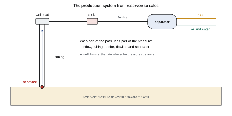
The production system is the whole path that oil, water and gas follow from the reservoir to the point of sale. It starts in the rock, where fluid flows through the pores toward the well. It enters the wellbore at the sandface, either through perforations or through the face of an open hole. It rises up the tubing to the wellhead, passes through a choke that controls the rate, travels along a flowline to a separator at a battery or pad facility, and is split into gas, oil and water. Each stream is then treated, measured and sent to a sales line, storage tank or disposal well.
The driving force for all of this movement is the pressure in the reservoir. Every component of the path resists flow and consumes part of that pressure: porous rock near the well, the completion, the vertical column of fluid in the tubing, friction, the choke, the flowline and the separator. The well flows at the rate at which the pressure the reservoir can supply at that rate exactly equals the pressure the rest of the system needs. That balance is the central idea of production engineering, and lesson 6 turns it into a method called nodal analysis.
Where the pressure goes
A useful first step with any well is a pressure budget, listing the pressure at each point along the path and the drop between them. The drops show where the system is spending its pressure and therefore where improvements could make the most difference.
# The production system as a pressure budget: where the reservoir's pressure is spent on the way to the sales line
SI = True
if SI:   # 04-22 Cardium horizontal early in its life; pressures in kPa
    u, nodes = "kPa", [("average reservoir pressure", 14600), ("sandface (bottomhole flowing)", 10250),
                       ("top of tubing (wellhead)", 1450), ("downstream of choke", 700),
                       ("separator inlet at the battery", 550), ("sales or gathering line", 450)]
    oil, water, gas, ou, gu = 52.0, 14.0, 5600.0, "m3/d", "m3/d"
    gor = gas / oil; gu2 = "m3/m3"
else:    # 4-22H Bakken horizontal early in its life; pressures in psi
    u, nodes = "psi", [("average reservoir pressure", 5300), ("sandface (bottomhole flowing)", 4300),
                       ("top of tubing (wellhead)", 650), ("downstream of choke", 300),
                       ("separator inlet at the pad", 160), ("sales or gathering line", 95)]
    oil, water, gas, ou, gu = 1050.0, 560.0, 900.0, "STB/d", "Mscf/d"
    gor = gas * 1000 / oil; gu2 = "scf/STB"
total = nodes[0][1] - nodes[-1][1]
names = ["reservoir to sandface (inflow)", "up the tubing", "across the choke", "flowline", "separator and treating"]
print(f"total pressure available: {total:,} {u}")
for (a, pa), (b, pb), n in zip(nodes, nodes[1:], names):
    print(f"   {n:32s} {pa - pb:7,} {u}  ({(pa - pb) / total:4.0%})")
wc = water / (oil + water)
print(f"daily test: oil {oil:,.0f} {ou}, water {water:,.0f} {ou}, gas {gas:,.0f} {gu}")
print(f"water cut {wc:.0%}, gas-oil ratio {gor:,.0f} {gu2}")total pressure available: 14,150 kPa reservoir to sandface (inflow) 4,350 kPa ( 31%) up the tubing 8,800 kPa ( 62%) across the choke 750 kPa ( 5%) flowline 150 kPa ( 1%) separator and treating 100 kPa ( 1%) daily test: oil 52 m3/d, water 14 m3/d, gas 5,600 m3/d water cut 21%, gas-oil ratio 108 m3/m3
For the 04-22, Ethan finds that about 31 percent of the 14,150 kPa available is spent moving oil through the rock to the well and about 62 percent is spent lifting the fluid up 1,500 m of tubing. The choke, flowline and separator together take only about 7 percent. That pattern is typical of a vertical lift problem: the column of liquid in the tubing weighs far more than friction anywhere else. It also hints at what will happen as the well ages. When reservoir pressure falls by a few thousand kilopascals, there will not be enough left to hold up the tubing column, and the well will need artificial lift.
Rates, ratios and units
Production engineers describe a well with a small set of numbers that appear on every test sheet.
Oil rate is measured at stock-tank conditions, in cubic metres per day (m³/d) in Canada. Water rate is also in m³/d. Gas rate is in cubic metres per day at standard conditions of 15 °C and 101.325 kPa. Regulators and many companies still quote barrels and thousand cubic feet, so engineers keep the conversions at hand: 1 m³ is about 6.29 barrels and 1,000 m³ of gas is about 35.3 thousand cubic feet.
Gross liquid or total fluid is oil plus water. Water cut is water divided by gross liquid, as a fraction or percentage. Gas-oil ratio (GOR) is gas divided by oil, in m³/m³; gas-liquid ratio (GLR) is gas divided by gross liquid. GLR matters more than GOR for lift, because the gas has to lift the water as well as the oil.
Pressures need care with reference. Bottomhole pressures for inflow calculations are absolute, while gauges at the wellhead read gauge pressure. Depths also need care: inflow equations use true vertical depth for hydrostatic pressure, while tubing friction depends on measured depth along the hole. In a horizontal well with a long lateral, the two differ by thousands of metres or feet.
Natural flow and artificial lift
A well flows naturally as long as the reservoir pressure, less the losses in the rock and completion, can push the fluid column to surface against the wellhead pressure. Gas in solution helps a great deal: as the fluid rises and the pressure falls, gas comes out of solution, lightens the column and expands. Water does the opposite, because it is heavier than oil and carries no gas.
Most oil wells lose their ability to flow at some point. Reservoir pressure falls as fluid is withdrawn, water cut usually rises, and the gas-liquid ratio may rise or fall. Before the well dies, or sooner if the gain pays, the production engineer adds artificial lift: a pump that reduces the pressure needed at the bottom of the well, or injected gas that lightens the fluid column. The main methods are sucker-rod pumping, gas lift, electric submersible pumps, progressing cavity pumps, plunger lift and hydraulic pumps. Lessons 8 to 10 cover them in turn.
In the Cardium, most wells go on rod pumps within months, because the reservoir pressure is modest and the depth is shallow enough for rods to work efficiently. Marisol tells Ethan to plan on the 04-22 needing lift by about its sixth month and to prove that estimate with numbers rather than habit.
Measurement and allocation
Production engineering depends on good numbers, and the numbers come from measurement. Most wells do not have their own permanent meters. Instead, each well is switched periodically into a test separator that measures its oil, water and gas for a period of hours. The battery or pad facility measures the total sales and disposal volumes continuously, and the total is allocated back to each well in proportion to its tests. Allocation determines royalties, regulatory reports and the decline curves that reservoir engineers use, so a well that is tested rarely or poorly can mislead everyone downstream.
In Alberta, the Alberta Energy Regulator (AER) sets measurement requirements, including how often wells must be tested and how volumes are reported to the provincial reporting system. Ethan learns that a production engineer is expected to know which wells are near the limits of those requirements and to flag test results that look wrong before they are reported.
The production engineer's tools
The core analytical tools of the course fit together. Inflow performance (lessons 2 and 3) describes how much fluid the reservoir delivers for a given bottomhole pressure. Outflow or tubing performance (lessons 4 and 5) describes the bottomhole pressure needed to lift a given rate to surface. Nodal analysis (lesson 6) combines the two to predict the operating rate and to test changes such as smaller tubing or lower wellhead pressure. Choke and surface calculations (lessons 7 and 11) close the loop at the top of the system. Artificial lift design (lessons 8 to 10) changes the outflow side, and surveillance (lesson 12) checks whether the predictions hold.
Modern production engineers do most of these calculations in commercial software, but the software uses the same equations, and an engineer who cannot check its answer with a quick hand calculation will eventually be fooled by it. This course therefore builds each method from first principles in short Python programs that can be run and changed.
Worked problem
A first look at a test sheet
A Cardium well tests 18 m³/d of oil, 27 m³/d of water and 2,200 m³/d of gas. Calculate the gross liquid, water cut, GOR and GLR.
Show solution
- Gross liquid = 18 + 27 = 45 m³/d.
- Water cut = 27/45 = 0.60, or 60 percent.
- GOR = 2,200/18 = 122 m³/m³.
- GLR = 2,200/45 = 49 m³/m³: the gas has to lift more than twice as much liquid as the oil alone.
Answer: High water cut cuts the effective gas-liquid ratio, which is why wells often stop flowing as water cut rises even when the gas-oil ratio is steady.
Safety and responsibility
Production operations handle pressure, flammable gas and, in many fields, hydrogen sulphide. The production engineer's designs set the pressures that equipment must contain and the procedures that field crews follow. Every change to a well or facility, from a new choke size to a pump replacement, goes through the company's management of change process, which checks pressure ratings, relief capacity and the effect on other equipment. Ethan's first lesson from Marisol is that the cheapest barrel is never one that puts an operator at risk.
Common mistakes
MistakeTreating the wellhead pressure as the start of the problem.
InsteadStart at the reservoir; most of the pressure is spent before fluid reaches the wellhead.
MistakeUsing gas-oil ratio to judge lift.
InsteadUse gas-liquid ratio, because the gas must lift the water too.
MistakeMixing gauge and absolute pressures in one calculation.
InsteadConvert to absolute before using inflow or gas equations.
MistakeConfusing measured and true vertical depth.
InsteadUse true vertical depth for hydrostatic pressure and measured depth for friction.
MistakeTrusting allocated rates without checking tests.
InsteadReview test frequency and quality before using rates for decisions.
Summary and key terms
- The production engineer keeps wells producing at the best rate and lowest cost the reservoir allows.
- The production system runs from the reservoir through the sandface, tubing, choke, flowline and separator.
- Each component consumes pressure; the well flows where supply and demand balance.
- In most oil wells the tubing column consumes the largest share of pressure.
- Water cut, GOR and GLR describe the fluid; GLR controls lift.
- Artificial lift is added when natural flow fails or when it pays to produce faster.
- Production system
- The path from reservoir to sales, including rock, completion, tubing, choke, flowline and facilities.
- Sandface
- The point where fluid leaves the rock and enters the wellbore.
- Water cut
- Water rate divided by total liquid rate.
- Gas-liquid ratio
- Gas rate divided by total liquid rate.
- Artificial lift
- Pumps or injected gas that help lift fluid when reservoir pressure is not enough.
- Allocation
- Dividing measured facility volumes among wells in proportion to their tests.
- Test separator
- A vessel that measures one well at a time for a period of hours.
Practice problems
Work each problem on paper first, then reveal the answer to check.
Why is the tubing usually the largest pressure loss in an oil well?
Show answer
The weight of the liquid column in the tubing is large compared with friction losses elsewhere.
A well's water cut rises from 20 to 60 percent at the same GOR. What happens to its GLR?
Show answer
It falls by half, because the same gas must lift twice as much liquid.
Which depth is used for hydrostatic pressure in a horizontal well?
Show answer
True vertical depth.
Why does allocation matter to reservoir engineers?
Show answer
Allocated well rates feed decline curves and reserves estimates.
Lesson quiz · 5 questions
Score 60% or more to complete this lesson.
Create a free account to save your progress, take quizzes and earn a certificate.