
MEC-499 · Lesson 5 of 12 · 22 min
Embodiment design, manufacturability and tolerancing
A concept is an idea with a sketch. Embodiment turns it into a coherent physical layout: where every major component sits, how they connect, how loads pass from one to another, how the product is made, assembled, transported and serviced, and what dimensions and tolerances hold it together. Most of a product's cost and many of its failures are decided here, long before the detailed drawings. Studies of product development often quote figures suggesting that the large majority of a product's lifetime cost is committed by the end of the design stage while only a small fraction has been spent, which is why a week spent on good embodiment saves months later.
For the TDX-150, embodiment ran from week 6 to week 10. This lesson follows three threads: the layout and mass budget, design for manufacture and assembly, and the tolerances that let a diesel engine drive a pump through a flexible coupling.
Layout
Hannah started the layout in CAD from the largest, least changeable parts: the engine, the pump wet end and the fuel tank. The engine is a three-cylinder industrial diesel of about 30 kW continuous rating at 1,800 rpm, chosen from a maker whose dealers the cooperative's mechanics already use. The pump is Tidewater's 150 mm self-priming wet end. The engine and pump are directly coupled: an adapter plate bolts to the engine's standard flywheel housing, the pump bracket bolts to the adapter, and a flexible coupling joins the flywheel to the pump shaft. That arrangement, used widely on engine-driven pumps, keeps the engine and pump aligned by machined spigots rather than by adjusting shims on site.
Placement followed function. The pump sits at the end of the skid nearest the water, with its suction inlet low and close to the end, so the suction hose is as short and as low as possible. The fuel tank sits between the frame rails under the engine, keeping the centre of mass low and close to the middle so the skid stays level when lifted from its single lifting eye. The radiator faces upward, an idea from the TRIZ session, pushing hot air and fan noise up rather than toward neighbouring homes. The control panel faces the side the crews will stand on, away from the exhaust.
Layout also means space for people. Rafael checked that every daily check point, the engine oil dipstick, the coolant level, the fuel filter, the priming separator's sight glass and the strainer, could be reached without removing a panel, and that a person in winter gloves could operate every valve. He used a simple rule: if it is checked every day, it must be visible and reachable with the canopy closed.
The mass budget
Mass was the characteristic the house of quality ranked equal first, so the team kept a mass budget from the first layout onward. A budget lists every major item with its estimated mass, the source of the estimate and its confidence, and compares the total with the limit. The first estimate came out at 1,003 kg against the 950 kg limit, 53 kg over.
# Embodiment checks for the TDX-150: coupling alignment stack, mass budget and a DFA index
import math

# 1. Radial offset between engine crankshaft and pump shaft (mm, each a +/- limit)
stack = {"flywheel housing spigot (SAE bell)": 0.05, "adapter plate bore position": 0.08,
         "pump bracket spigot": 0.05, "pump bearing housing bore": 0.04,
         "pump shaft runout at hub": 0.03, "coupling hub bore clearance": 0.02}
worst = sum(stack.values()); rss = math.sqrt(sum(v * v for v in stack.values()))
allow = 0.25    # flexible coupling: parallel offset allowed for full rated life
print(f"Offset worst case {worst:.3f} mm, RSS {rss:.3f} mm, coupling allows {allow:.2f} mm")
stack["adapter plate bore position"] = 0.05     # bore position held to 0.05 by machining after welding
print(f"With adapter bore at 0.05: worst case {sum(stack.values()):.3f} mm")

# 2. Wet mass budget (kg) against the 950 kg limit
mass = {"diesel engine with radiator": 290, "pump wet end and bracket": 210,
        "frame and lifting points": 180, "fuel (200 L full)": 168, "vacuum priming system": 35,
        "battery, controls and wiring": 30, "acoustic canopy (steel)": 90}
m = sum(mass.values()); print(f"First mass estimate {m} kg  ->  over by {m - 950} kg")
mass["acoustic canopy (steel)"] = 45          # aluminium canopy panels
mass["frame and lifting points"] = 155        # lighter side rails after analysis
m2 = sum(mass.values()); print(f"After changes {m2} kg  ->  margin {950 - m2} kg ({(950 - m2) / 950:.1%})")

# 3. Boothroyd-Dewhurst design-for-assembly index: 3 s ideal time per essential part
def dfa(parts, essential, time_s): return 3 * essential / time_s
before = dfa(parts=46, essential=14, time_s=412)
after = dfa(parts=27, essential=14, time_s=236)
print(f"Priming system DFA index {before:.2f} -> {after:.2f} (parts 46 -> 27)")Offset worst case 0.270 mm, RSS 0.120 mm, coupling allows 0.25 mm With adapter bore at 0.05: worst case 0.240 mm First mass estimate 1003 kg -> over by 53 kg After changes 933 kg -> margin 17 kg (1.8%) Priming system DFA index 0.10 -> 0.18 (parts 46 -> 27)
Two changes closed the gap. The acoustic canopy, first drawn in 1.2 mm galvanized steel, was redrawn in aluminium of equal stiffness, saving about 45 kg; lesson 7 explains that choice and its acoustic cost. The frame rails were reduced from a 152 by 76 mm hollow section to 127 by 64 mm once Kwame's analysis, covered in lesson 6, showed the rails were far stronger than needed. The new total of 933 kg leaves a margin of 17 kg, under 2 per cent. That is thin. Mass estimates usually grow as detail is added: fasteners, brackets, wiring and paint all add up. Professor Leger's rule of thumb is to hold at least 5 per cent margin at this stage. The team logged the thin margin as a risk, with two fallbacks: a lighter battery and control enclosure, and, as a last resort, a 160 L tank, which would give only about 21 hours at the rated point and would need the client's agreement to relax R-06.
Design for manufacture and assembly
Design for manufacture asks whether each part can be made easily and cheaply with the processes available. Design for assembly asks whether the parts can be put together quickly, correctly and with as few parts as possible. Together, DFMA is one of the most effective tools for reducing cost, because the cost of a product is driven not just by its materials but by the number of parts, the operations to make each one and the minutes to assemble them.
Boothroyd and Dewhurst's design-for-assembly method asks of each part three questions: does it move relative to other parts in normal operation, must it be of a different material from the parts it touches, and must it be separate to allow assembly or service? If the answer to all three is no, the part is a candidate for elimination, usually by combining it with a neighbour. Their assembly efficiency index compares the ideal assembly time, about 3 seconds for each theoretically necessary part, with the actual estimated time:
Hannah applied the method to the vacuum priming system, which in its first layout had 46 parts: a vacuum pump, a belt drive with tensioner, a float-valve separator, a non-return valve, six hose clamps, four elbows, brackets, fasteners and a manual isolation valve. Fourteen parts passed the three questions. By driving the vacuum pump directly from an engine power take-off instead of a belt, mounting the separator directly on the pump casing so its inlet is a machined port rather than a hose, and replacing loose clamps and elbows with a single moulded hose, she reduced the count to 27 and the estimated assembly time from 412 to 236 seconds. The index rose from 0.10 to 0.18. Both values are low by mass-production standards, which is typical for a welded, low-volume product, but the improvement removed eleven potential leak points from the system that lesson 8 will identify as the most likely cause of lost prime.
Design for manufacture produced other changes. Hannah redrew the canopy panels so all bends had the same inside radius and could be formed with one press-brake tool; replaced three different bolt sizes on the frame with one; and arranged the frame so that all welds could be made from above in one jig, without turning the frame over. Marco Rossi, Tidewater's quality manager, reviewed the drawings and asked for one more change: every hole that locates another part should be drilled after welding, not before, because welding distorts the frame and pre-drilled holes would not line up.
Tolerances and the coupling alignment stack
A flexible coupling tolerates some misalignment between the shafts it joins, but every bit of misalignment costs life: in the elastomer element, in the pump bearings and in the engine crankshaft's rear bearing. The coupling the team selected allows 0.25 mm of parallel offset for its full rated life. Six features lie in the chain between the engine crankshaft axis and the pump shaft axis, each with its own tolerance, as the figure shows.
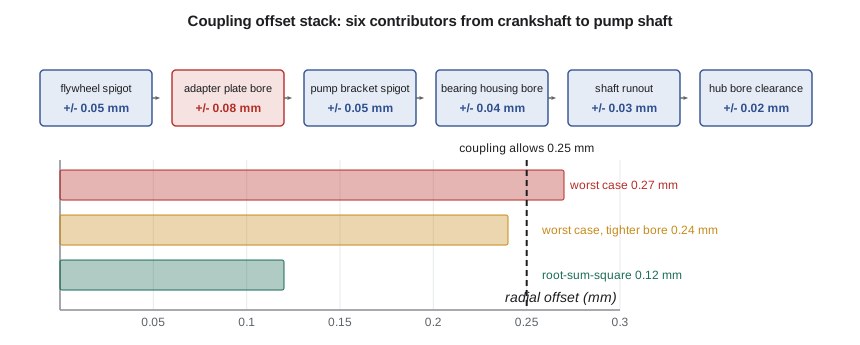
There are two ways to add tolerances in a stack. The worst-case method assumes every feature is at its limit in the same direction at once, and simply sums the tolerances. It guarantees assembly but is pessimistic. The statistical, or root-sum-square, method assumes the deviations are independent and roughly normally distributed, so they combine like variances:
The worst case is 0.27 mm, over the 0.25 mm allowance; the root-sum-square is 0.12 mm, well under. Which to believe? For six independent features, the statistical estimate describes what most assemblies will see, and the worst case is very unlikely. But the team intended to build only six units, and for small quantities the assumptions behind the statistical method, centred and independent processes, are hard to verify. A single adapter plate machined off-centre would put that skid near the worst case. The largest contributor was the position of the bore in the adapter plate, a welded plate whose bore was to be machined before welding. Moving that operation to after welding, in the same set-up as the mounting face, tightened its position tolerance to 0.05 mm and brought the worst case to 0.24 mm, inside the allowance. The team chose a design that works at worst case, because the cost was one machining operation.
Geometric dimensioning and tolerancing
Plus-or-minus dimensions describe sizes well but locations poorly, because they do not say which surface a measurement starts from. Geometric dimensioning and tolerancing, standardized in North America in ASME Y14.5 (the 2018 edition, reaffirmed in 2024) and internationally in the ISO geometrical product specification standards, describes the function of each feature directly. Datums are the surfaces from which the part is located in assembly. Feature control frames state the type of tolerance, its size and the datums it refers to.
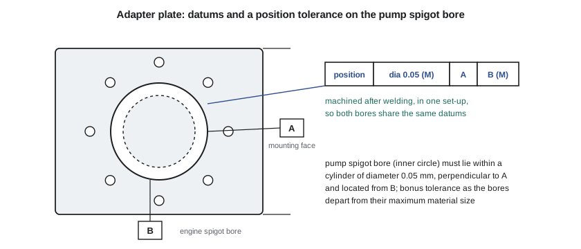
On the adapter plate, datum A is the face that bolts to the engine's flywheel housing, and datum B is the bore that fits the housing's spigot. The pump spigot bore carries a position tolerance of 0.05 mm diameter relative to A and B. In plain words, its axis must lie inside a cylinder 0.05 mm across, perpendicular to the mounting face and centred on the engine spigot. The modifier for maximum material condition allows extra tolerance when the bores are larger than their smallest permitted size, because a looser fit can absorb a little more position error and still assemble. GD&T makes the designer's intent unambiguous to the machinist and the inspector, and lets Marco's inspectors check the part with a fixture that mimics its real mounting.
Worked problem
A gap stack for the coupling guard
The fixed guard over the coupling must clear the rotating coupling by at least 6 mm. Nominal clearance is 10 mm, and the contributors are guard bracket position ±1.5 mm, guard sheet forming ±1.0 mm, coupling outside diameter ±0.5 mm and adapter flange position ±1.0 mm. Is the worst case acceptable?
Show solution
- Worst-case variation: 1.5 + 1.0 + 0.5 + 1.0 = 4.0 mm.
- Minimum clearance: 10 − 4.0 = 6.0 mm, exactly at the limit.
- Root-sum-square: √(2.25 + 1.0 + 0.25 + 1.0) = 2.12 mm, giving 7.9 mm typically.
- Because the guard is a safety part and a rubbing coupling could wear through it, the team increased the nominal clearance to 12 mm, giving 8.0 mm at worst case.
Answer: The worst case only just meets 6 mm; for a safety part the team added margin rather than relying on statistics.
Design for service, transport and use
Embodiment is also where the product's whole life is designed. The cooperative's mechanics will change oil, filters and the coupling element. Hannah arranged the canopy in four lift-off panels, each under 12 kg, so one person can open it. The skid has forklift pockets sized for the cooperative's warehouse forklift, four tie-down points rated for transport, and a single central lifting eye placed over the centre of mass so a crane can lift it level. Rafael added a drip tray under the engine that drains to the fuel containment, so oil leaks during service do not reach the ground or the floodwater.
Common mistakes
MistakeStarting the layout from small parts.
InsteadPlace the largest, least changeable parts first, then arrange the rest by function and access.
MistakeCarrying a mass budget with almost no margin.
InsteadHold margin early, since estimates grow with detail, and log a fallback if the margin is thin.
MistakeRelying on root-sum-square stacks for small production quantities.
InsteadCheck the worst case, especially for few units or safety-critical fits, and tighten the largest contributor.
MistakeDimensioning locations with plus-or-minus from arbitrary edges.
InsteadUse datums and geometric tolerances that reflect how the part is located in assembly.
MistakeDrilling locating holes before welding.
InsteadMachine or drill locating features after welding, so distortion does not misplace them.
Summary and key terms
- Embodiment fixes layout, interfaces, manufacture, assembly, service and tolerances, and commits most of the product's cost.
- The engine and pump are directly coupled through an adapter plate and flexible coupling, aligned by machined spigots.
- The mass budget fell from 1,003 kg to 933 kg with an aluminium canopy and lighter rails, leaving under 2 per cent margin.
- DFA reduced the priming system from 46 to 27 parts and raised its index from 0.10 to 0.18, removing leak points.
- The coupling offset stack was 0.27 mm worst case against a 0.25 mm allowance; machining the adapter after welding brought it to 0.24 mm.
- GD&T with datums A and B and a position tolerance states the adapter plate's function unambiguously.
- Embodiment design
- Developing a concept into a coherent layout with interfaces, materials and processes.
- Mass budget
- A controlled list of component masses compared with a limit, with margin.
- DFMA
- Design for manufacture and assembly: reducing parts, operations and assembly time.
- Assembly efficiency index
- Ideal assembly time for essential parts divided by estimated assembly time.
- Tolerance stack-up
- The accumulation of tolerances along a chain of features.
- Worst-case stack
- The sum of all tolerances, assuming each is at its limit.
- Root-sum-square stack
- The square root of the sum of squared tolerances, for independent variations.
- Datum
- A theoretically exact surface or axis from which features are located.
- Feature control frame
- A GD&T box stating tolerance type, size, modifiers and datums.
- Maximum material condition
- The size at which a feature contains the most material; bonus tolerance applies as it departs.
Practice problems
Work each problem on paper first, then reveal the answer to check.
Tolerances of 0.10, 0.05, 0.05 and 0.02 mm. Give the worst-case and RSS totals.
Show answer
Worst case 0.22 mm; RSS √(0.01 + 0.0025 + 0.0025 + 0.0004) = 0.124 mm.
A product has 18 essential parts and assembles in 240 s. What is its DFA index?
Show answer
3 × 18 / 240 = 0.225.
The mass budget is 940 kg against 950 kg. What margin is that, and is it enough at embodiment?
Show answer
10 kg, about 1 per cent; too little, since estimates usually grow.
Why does a single central lifting eye need to be over the centre of mass?
Show answer
So the skid lifts level and does not tilt, which would load slings unevenly and could shift fuel.
What does the maximum material condition modifier allow on the adapter plate bore?
Show answer
Extra position tolerance as the bore departs from its smallest size, since a looser fit still assembles.
Lesson quiz · 5 questions
Score 60% or more to complete this lesson.
Create a free account to save your progress, take quizzes and earn a certificate.